


11
3.3.3 Continuity Monitoring (if open / short option was ordered)
When two wires are connected to each probe, cable continuity testing is
continuously performed. Connect one wire from the “E” (electrode)
terminal to the probe and another wire from the “S” (sense) terminal to
the probe. If either of these wires are broken or shorted or a probe is
shorted, a continuity fault occurs, the electrical fault relay is de-
energized, the Electrical Fault LED on the display is turned on and a
yellow LED corresponding to the channel is turned on. (Ref: fig 6, loc 9).
If the break is in the wire connected to the “S” terminal, the level will still
show proper steam/water status. If the break is in the wire connected to
the “E” terminal, that channel will always show steam. If single wiring
only is used, the continuity function will not work.
(Refer to fig 6, loc 8).
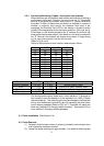
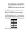
Tables of test points and fault condition determination follow.
Probe # Left TP# Right TP# LED #
12 26 27 15
11 35 36 21
10 38 39 23
9 41 42 25
8 29 30 17
7 32 33 19
6 23 24 13
5 17 18 9
4 20 21 11
3 14 15 7
2 11 12 5
1 8 9 3
Condition Left TP Right TP Note
Normal Operation
≈ +9 VDC ≈ -9 VDC
Normal Display/ Relay
Short < +1 VDC > -1 VDC Display and Relay indicates water
“E” wire open < +1 VDC
≈ -9 VDC
Display and Relay indicates steam
“S” wire open
≈ +9 VDC
> -1 VDC Steam/Water Display and Relays Normal
The shorted probe option works with a fixed reference. It changes to
fault condition upon the detection of the equivalent of ≈1000 μS water
(standard setting). This switching point may be changed to indicate fault
at any user determined conductivity point by replacing the three short-
circuit resistor packages (Refer to fig 6, loc 7). If applied, this option will
allow early detection of changing water chemistry. See section 5.3 for
more details on changing resistor packages.
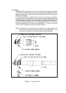
3.4 Probe Installation (See Section 2.4)
3.5 Probe Removal
(1) Ascertain that the water column is properly isolated from the steam drum
and all pressure has been relieved.
(2) Loosen the probe retaining nut approximately 1 turn and then free the probe