


7
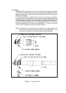
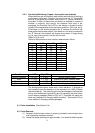
2.6.3.1 Flash Programming (refer to fig 6, loc 17)
For operationally critical point indication – any green (water) or
red (steam) LED on all displays may be user programmed to
flash. As supplied all LED’s are programmed steady state.
There are two columns each three pins wide. Red LED control
is the left three pin columns; green, the right three pin columns.
If the shorting link is placed on the right two pins in a color
column, that LED color/channel will be steady state.
If the shorting link is moved to the left two pins in a column, that
LED color/channel will flash. Probe numbers, color and F(lash)
/ S(teady state) are silk screened on the printed circuit board as
a guide. The flash oscillator frequency may be checked with an
oscilloscope at test point #7 as a 5V ≈ 3Hz square wave.
Note: Do NOT set any of the LED’s to flash if a 4-20mA output
module is used with the system. This will interfere with the
proper operation of the 4-20mA module.
2.6.4 Control Output (water fail-safe) (refer to fig 6, loc 10)
SPDT Form-C contacts are provided for the control output of each
channel. These outputs are designated Relays “1” through “12” for
channels 1 through 12, respectively. Contact Rating:
8 A @ 28 VDC
10 A @ 120 Vac
10 A @ 250 Vac CSA and UL
5 A @ 250 Vac TÜV
Careful consideration should be given to the design of the alarm and trip
logic. Power loss or vessel blowdown could inadvertently shut down the
steam generator or leave the unit without protection. A keyed lock-out
switch, for trips, alarms, etc. is available as an option. The NC/NO/C
terminals are graphically marked at each relay. See detail on fig 4.
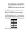
2.6.5 Electrical Fault Output (fail-safe)
A SPDT Form-C relay contact is provided to monitor the operation of the
Model 12B. This relay coil is normally energized. Loss of power to the
unit or detection of an internal Electrical Fault condition will cause the
relay to de-energize, opening the contacts. The electrical fault detection
circuit covers clock failure, open and short circuit detection and two
internal power supplies. This feature has variable time delay from 3 to
about 10 seconds. See fig 6, loc 12 for the adjustment potentiometer.
Turn clockwise to increase the length of delay.
2.6.6 Level Fault Output (fail-safe)
The Model 12B is also equipped with a Level Fault relay. A Level Fault
occurs whenever water is detected above steam. Probe 1 is always at
the lowest level. This feature also has variable time delay. The
adjustment potentiometer is on fig 6, loc 13. Turn clockwise to increase
the length of delay.