


66 UNT-SVX07A-EN
Maintenance
troubleshooting
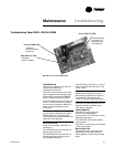
Manual Output Test Procedure
Follow the procedure below to test the
Tracer ZN010, ZN510, and ZN520
controllers.
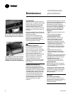
1. Press and hold the TEST button for at
least two seconds (not exceeding 5
seconds), and then release, to start the
test mode.
2. The test sequence will turn off all
outputs and then attempt to clear all
diagnostics.
3. Press the TEST button several more
times (no more than once per second)
to advance through the test sequence.
The outputs are not subject to minimum
times during the test sequence. However,
the test sequence only permits one step
per second which limits minimum output
time.
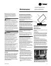
The green LED is turned off when the
TEST button is pressed. To begin the
manual output test mode, press and hold
the TEST button (turning off the green
LED) for at least two seconds.The green
LED will begin to blink, indicating the
controller is in test mode.
Table M-T-1. Test sequence for 1-heat/1-cool configurations
steps fan cool output heat output damper
BOP1-3 BOP4 (1) BOP5 BOP6
1. off off off off closed
2. fan High high off off closed
3. fan medium medium off off closed
4. fan low low off off closed
5. cool high on off closed
6. heat high off on closed
7. fresh air high off off open
damper (3)
8. exit (2)
Notes:
(1) At the beginning of step 2, the controller attempts to clear all diagnostics.
(2) For all 1-heat/1-cool applications including 2-pipe changeover, BOP4 energizes in
the cooling test stage and BOP5 energizes in the heat test stage.This occurs even
though during normal 2-pipe changeover operation BOP4 controls the unit valve
for both cooling and heating.
(2) After the Fresh Air Damper step, the test sequence performs the Exit step.This
initiates a reset and attempts to return the controller to normal operation.
(3) The fresh air damper (BOP6) only energizes during this step if binary output 6
has been configured as a fresh air damper.
• Verify output wiring and operation
without using Rover™, service tool
• Force the water valve to open and
balance the hydronic system
Note: The manual output test is not an
automatic cycle. You must press the
TEST button to proceed through each
step.
The controller observes all diagnostics
that occur during the test sequence.
Although an automatic diagnostic reset
sequence exists as part of the controller’s
normal operation, the automatic diagnos-
tic reset feature is not active during the
test sequence.
If left in an individual test step, the
controller remains in test mode for 60
minutes and then exits to normal
operation.
Many service calls are due to unit
diagnostics. The test sequence resets
unit diagnostics and attempts to restore
normal unit operation prior to testing the
outputs. If the diagnostics remain after a
reset, the STATUS LED indicates the
diagnostic condition is still present (two
blinks).