


6 UNT-SVX07A-EN
J = 2-way, modulating, 0.7 Cv (50 psig)*
K = 3-way, modulating, 0.7 Cv (50 psig)*
L = 2-way, modulating, 1.1 Cv (60 psig)*
M= 3-way, modulating, 1.1 Cv (60 psig)*
N = 2-way, modulating, 2.3 Cv (60 psig)*
P = 3-way, modulating, 2.7 Cv (60 psig)*
Q = 2-way, modulating, 3.3 Cv (60 psig)*
R = 3-way, modulating, 3.8 Cv (60 psig)*
X = field-supplied, NO
Y = field-supplied, NC
Z = field-supplied 3-wire modulating
Digit 28 — auxiliary control valve
0 = none
A = 2-way, 2-position, NO (30 psig)
B = 3-way, 2-position, NC (28 psig)
C = 2-way, 2-position, NC (30 psig)
D = 3-way, 2-position, NC (20 psig)
E = 2-way, 2-position, NO (50 psig)
F = 3-way, 2-position, NO (28 psig)
G = 2-way, 2-position, NC (50 psig)
H = 3-way, 2-position, NC (28 psig)
J = 2-way, modulating, 0.6 Cv (60 psig)
K = 3-way, modulating, 0.6 Cv (60 psig)
L = 2-way, modulating, 1.1 Cv (60 psig)
M= 3-way, modulating, 1.1 Cv (60 psig)
N = 2-way, modulating, 2.3 Cv (60 psig)
P = 3-way, modulating, 2.7 Cv (60 psig)
Q = 2-way, modulating, 3.3 Cv (60 psig)
R = 3-way, modulating, 3.8 Cv (60 psig)
X = field-supplied, NO
Y = field-supplied, NC
Z = field-supplied 3-wire modulating
Digit 29 — piping packages
0 = none
A = basic ball valve S & R
B = basic ball valve S/man. crkt set
C = basic ball valve S & R w/auto crkt set
D = deluxe ball valve S & R
E = deluxe ball valve S /man. crkt set R
F = deluxe ball valve S & R w/auto crkt set
Digit 30 — control type
0 = none
A = fan speed switch
E = Tracer ZN010
F = Tracer ZN510
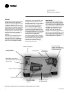
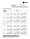
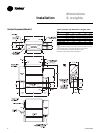
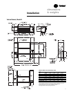
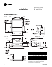
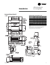
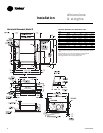
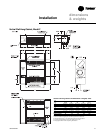
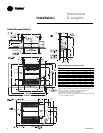
Installation
general
information
G = Tracer ZN520
H = CSTI
Digit 31 — control option
D = unit mtd fan mode, unit voltage,
K = wall mtd fan mode
V = unit mtd fan sp w/ setpnt
X = unit mtd fan sp w/ wall mtd setpnt
Y = unit mtd fan sp & wall mtd setpnt w/
comm.
Z = unit mtd fan sp, on/cancel, setpnt w/
comm.
1 = wall mtd on/cancel w/ comm.
2 = wall mtd fan speed, setpnt, on/cancel
w/ comm.
3 = unit mtd fan speed switch, low voltage
4 = wall mtd digital zone sensor, fan sp w/
setpnt, on/cancel, comm.
5 = wall mtd digital zone sensor, setpnt,
on/cancel, comm.
Digit 32 — IAQ options
0 = none
1 = dehumidification
4 = dehumidification w/sensor
Digit 33 — cntrl function #1
0 = w/o exhaust fan/damper or alarm
Digit 34 — cntrl function #2
0 = w/o occupant call or IAQ status
Digit 35 — control function #3
0 = none
1 = occ/unocc control
2 = condensate overflow detection
3 = occ/unocc & condensate overflow
Digit 36 — cntrl function #4
0 = none
1 = smoke input
2 = low temperature detection
3 = smoke input & low limit sensor
Digits 37, 38 — future cntrl functions
Digit 39 —
projection panel/falseback
0 = none
A =
5
/
8
”standard vertical recessed panel
B = 2” projection panel
C = 2.5” projection panel
D = 3” projection panel
E = 3.5” projection panel
F = 4” projection panel
G = 4.5” projection panel
H = 5” projection panel
J = 5.5”projection panel
K = 6” projection panel
L = 2”falseback
M = 3” falseback
N = 4” falseback
P = 5” falseback
Q = 6” falseback
R = 7” falseback
T = 8” falseback
Digit 40 — main autoflow gpm
A = 0.5 G = 3.0 N = 7.0
B = 0.75 H = 3.5 P = 8.0
C = 1.0 J = 4.0 Q = 9.0
D = 1.5 K = 4.5 R = 10.0
E = 2.0 L = 5.0 T = 11.0
F = 2.5 M= 6.0 U = 12.0
Digit 41 — auxiliary autoflow gpm
A = 0.5 F = 2.5 L = 5.0
B = 0.75 G = 3.0 M= 6.0
C = 1.0 H = 3.5 N = 7.0
D = 1.5 J = 4.0 P = 8.0
E = 2.0 K = 4.5
Digit 42 — subbase
0 = none
A = 2” subbase D =5” subbase
B = 3” subbase E =6” subbase
C = 4” subbase F =7” subbase
Digit 43 — recessed flange
0 = none
A = recessed flange
Digit 44 — wall boxes
0 = none
A = anodized wall box