


UNT-SVX07A-EN 35
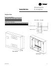
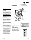
mechanical
requirementsInstallation
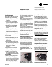
Steam Piping
CAUTION
Coil Damage!
In all steam coil installations, the
condensate return connections must
be at the low point of the coil to
ensure condensate flows freely from
the coil at all times. Failure to do so
may cause physical coil damage from
water hammer, unequal thermal
stresses,freeze-up and/or corrosion.
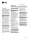
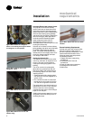
1. Make piping connections to the steam
coil as shown in Figure I-MR-11. Cap the
unused connection.
2. The coil is already pitched within the
unit to provide proper pitch to drain
condensate out of the coil. Verify that
the unit has been properly leveled.
3. Install a
1
/
2
-inch, 15-degree swing check
vacuum breaker in the unused
condensate return tapping as close as
possible to the coil.
4. Vent the vacuum breaker line to
atmosphere or connect it into the return
main at the discharge side of the steam
trap.
5. Pitch all steam supply and return mains
down a minimum of one inch per ten
feet in the direction of flow.
6. Do not drain the steam mains or take-
off through the coils. Drain the mains
ahead of the coils through a steam trap
to the return line.
7. Overhead returns require one psig of
pressure at the steam trap discharge
for each two-feet elevation to ensure
continuous condensate removal.
8. Proper steam trap selection and
installation is necessary for satisfactory
coil performance and service life. For
installation, use the following steps:
a. Position the steam trap discharge at
least 12 inches below the condensate
return connection. This provides
sufficient hydrostatic head pressure to
overcome trap losses and ensure
complete condensate removal.
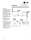
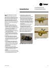
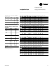
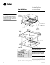
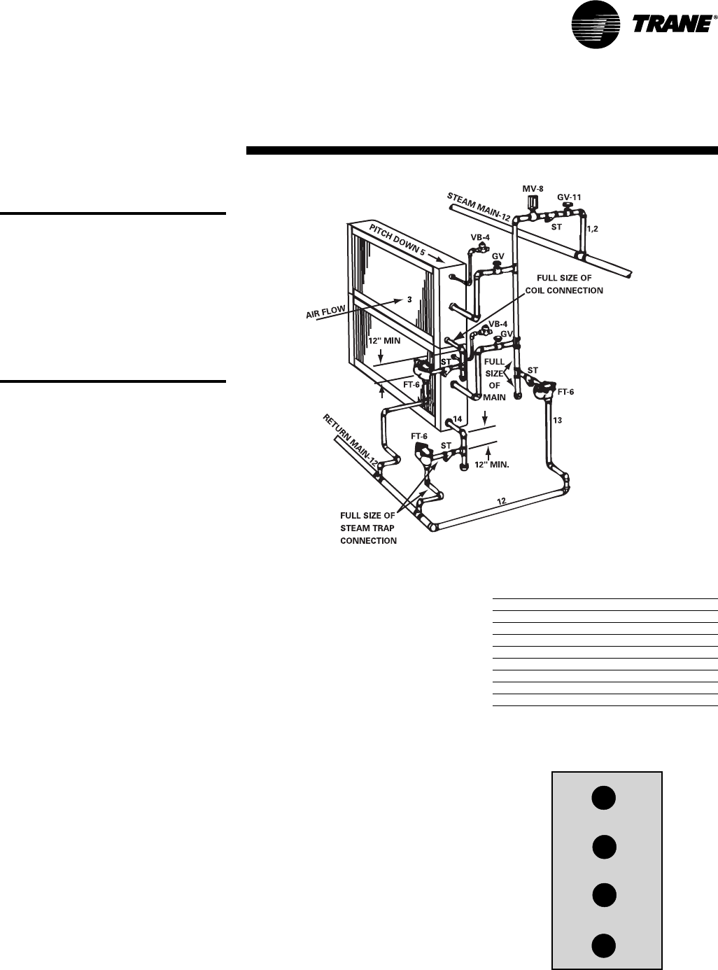
Figure I-MR-2. Typical Piping for Steam Coils
Code of System Components in Piping
Diagram
FT Float and thermostatic steam trap
BT Bucket steam trap
GV Gate valve
OV Automatic two-position (on-off) control valve
TV Automatic three-way control valve
VB Vacuum breaker
CV Check valve
ST Strainer
AV Automatic or manual air vent
b. Trane recommends using flat and
thermostatic traps because of gravity
drain and continuous discharge
operation.
c. Use float and thermostatic traps with
atmospheric pressure gravity
condensate return, with automatic
controls or where the possibility of low
pressure supply steam exists.
d. Always install strainers as close as
possible to the trap inlet side. Reference
Figure I-MR-10 for an example of a
properly piped steam coil.
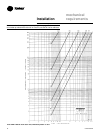
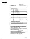
Figure I-MR-11. Main steam coil connection
diagram
vacuum breaker (if desired)
steam supply
plugged
condensate return