


52 UNT-SVX07A-EN
Operation
sequence of
operation
Analog Inputs
Both Tracer ZN010 and ZN510 accept a
maximum of five analog inputs.
Reference Table O-SO-4.
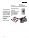
Zone Sensors
The zone sensors available with the
Tracer ZN010 and ZN510 provide up to
three different inputs
1. Space temperature measurement
(10KΩ thermistor)
2. Local setpoint
3. Fan mode switch
Wall mounted zone sensors include a
thermistor as a component of the
internal printed circuit board. Unit
mounted zone sensors use a sensor
placed in the unit’s return air stream.
Each zone sensor is equipped with a
thumbwheel for setpoint adjustment.
Fan Mode Switch
The zone sensor may be equipped with a
fan mode switch. The fan mode switch
offers selections of off, low, medium,
high, or auto.
Supply Fan Operation
Reference Table O-SO-5 for fan mode
operation. Reference Table O-SO-5 for
fan mode operation. Tracer ZN010 and
ZN510 will operate in either continuous
fan or fan cycling mode. The fan cycles
when the fan mode switch is placed in
auto. The fan runs continuous when
placed in the high, medium, or low
position. Use Rover, Trane’s installation
and service tool, to change auto defaults.
Table O-SO-4. Analog inputs
analog input description application
zone space temperature space temperature detection
set local setpoint thumbwheel setpoint
fan fan mode input zone sensor fan switch
analog input 1 (AI1) entering water temperature entering water temperature detection
analog input 2 (AI2) discharge air temperature discharge air temperature detection
Notes:
1.The zone sensor, entering water temperature sensor, and the discharge air temperature sensor are 10KΩ thermistors.
Figure 26 provides the resistance-temperature curve for these thermistors.
2. Zone sensor:
Wall mounted sensors include a thermistor soldered to the sensor’s circuit board
Unit mounted sensors include a return air sensor in the unit’s return air stream.
3. Changeover units include an entering water temperature sensor.
Table O-SO-6. Valid operating range and factory default setpoints
setpoint/parameter default setting valid operating range
unoccupied cooling setpoint 85° F 40 to 115° F
occupied cooling setpoint 74° F 40 to 115° F
occupied heating setpoint 71° F 40 to 115° F
unoccupied heating setpoint 60° F 40 to 115° F
cooling setpoint high limit 110° F 40 to 115° F
cooling setpoint low limit 40° F 40 to 115° F
heating setpoint high limit 105° F 40 to 115° F
heating setpoint low limit 40° F 40 to 115° F
power-up control wait 0 sec 0 to 240 sec
Table O-SO-5. Fan mode operation
heating mode cooling mode
fan mode occupied unoccupied occupied unoccupied
off off off off off
low low off/high (3) low off/high (3)
medium medium off/high (3) medium off/high (3)
high high off/high (3) high off/high (3)
auto
continuous heat default off/high (3) cool default off/high (3)
cycling off/heat default off/high (3) off/cool default off/high (3)
Notes:
1. During the transition from off to any fan speed but high, Tracer ZN010 and ZN510 automatically starts the fan on high
speed and runs for three seconds before transitioning to the selected speed (if it is other than high). This provides
enough torque to start all fan motors from the off position.
2. When the heating output is controlled off, Tracer ZN010 and ZN510 automatically controls the fan on for an additional 30
seconds. This delay allows the fan to dissipate any residual heat from the heating source, such as electric heat.
3. Whenever two states are listed for the fan:
The first state (off) applies when there is not a call for heating or cooling.
The second state (varies) applies when there is a call for heating or cooling.
The heat default is factory configured for low fan speed, and the cool default is medium.