


UNT-SVX07A-EN 49
Operation
general
information
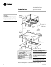
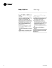
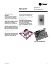
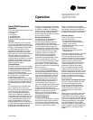
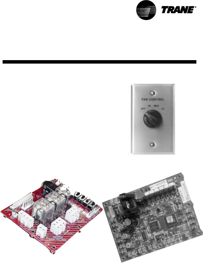
Figure O-GI-3. Tracer ZN010 board
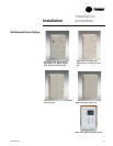
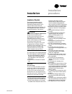
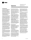
Figure O-GI-2. Fan speed switch
General Information
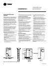
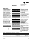
Relay Board
The relay board is a new component on
all models (except those with a unit-
mounted, line-voltage fan speed switch)
that replaces all the loose wires in the
control box. It consolidates many control
components onto one board, therefore
making it easy to troubleshoot in the field.
There is an LED on the board that
indicates when power is supplied to the
board. All connections are made to match
up only with the applicable component to,
thus prevent miswiring. Factory switches
are pre-set and locked in place with lock-
tight. The switch settings can be broken if
field-modifications are needed. However,
switches must be properly set for the unit
to operate safely and properly. See
Figure O-GI-1.
Manual Fan Mode Switch
The manual fan mode switch is available
with a four-position switch (off-hi-med-lo)
allows manual fan mode selection and is
available unit or wall mounted. See
Figure O-GI-2.
Figure O-GI-1. Relay board
The unit-mounted option operates on line
voltage. The wall mounted option is low-
voltage and has three 24-volt relays using
a factory-wired transformer and relays to
control the fan motor.
Tracer ZN010 & ZN510
Tracer ZN010 is a stand-alone device that
controls fan-coils and cabinet heaters.
Tracer ZN510 can be stand-alone or use
peer-to-peer communications.
The controller is easily accessible in the
control end panel for service. The control
end panel is on the end of the unit
opposite the piping. Reference Figure O-
GI-3.