


UNT-SVX07A-EN 63
Maintenance
diagnostics
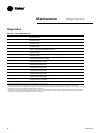
Table M-D-6. Electric Heat Not Operating
Probable Cause Explanation
Normal operation The controller cycles electric heat on and off to meet the unit capacity requirements.
Requested mode: off It is possible to communicate the operating mode (such as off, heat, cool) to the controller. When off is communicated to the controller,
the units shuts off the electric heat.
Communicated disable Numerous communicated requests may disable electric heat, including an auxiliary heat enable input and the heat/cool mode input.
Depending on the state of the communicated request, the unit may disable electric heat.
Manual output test The controller includes a manual output test sequence that verifies analog and binary output operation and associated output
wiring. However, based on the current step in the test sequence, the electric heat may not be on. Refer to the “Manual Output Test”
section.
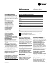
Diagnostic present A specific list of diagnostics affects electric heat operation. For more information, see the “Diagnostics” section.
Unit configuration The controller must be properly configured based on the actual installed end devices and application. When the unit configuration does
not match the actual end device, the electric heat may not work properly.
No power to the controller If the controller does not have power, electric heat does not operate. For the controller to operate normally, a
24VAC input voltage must be applied. Whenthe green LED is off continuously, the controller does not have sufficient power or has
failed.
Unit Wiring The wiring between the controller outputs and the electric heat contacts must be present and correct for normal electric heat
operation. Refer to the typicalunit wiring diagrams in the Appendix of this manual.
Table M-D-7. Fresh Air Damper Stays Open
Probable Cause Explanation
Normal operation The controller opens and closes the fresh air damper based on the controller’s occupancy mode and fan status. Normally, the
fresh air damper is open during moccupied mode when the fan is running and closed during unoccupied mode.
Manual output test The controller includes a manual output test sequence that verifies analog and binary output operation and associated output
wiring. However, based on thecurrent step in the test sequence, the fresh air damper may not be open. Refer to
the “Manual Output Test” section.
Unit configuration The controller must be properly configured based on the actual installed end devices and application. When the unit
configuration does not match the actualend device, the damper may not work correctly.
Unit wiring The wiring between the controller outputs and the fresh air damper must be present and correct for normal damper operation. Refer
to the typical unit wiringdiagrams in the Appendix of this manual.
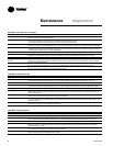
Table M-D-8. Fresh Air Damper Stays Closed
Probable Cause Explanation
Normal operation The controller opens and closes the fresh air damper based on the controller’s occupancy mode and fan status. Normally, the
fresh air damper is open during moccupied mode when the fan is running and closed during unoccupied mode.
Warmup and cooldown The controller includes both a warmup and cooldown sequence to keep the fresh air damper closed during the transition from
unoccupied to occupied. This is an attempt to bring the space under control as quickly as possible.
Requested mode: off It is possible to communicate the operating mode (such as off, heat, cool) to the controller. When off is communicated to the
controller, the unit closes the fresh air damper.
Manual output test The controller includes a manual output test sequence that verifies analog and binary output operation and associated output
wiring. However, based on thecurrent step in the test sequence, the fresh air damper may not be open. Refer to
the “Manual Output Test” section.
Diagnostic present A specific list of diagnostics effects fresh air damper operation. For more information, see the “Diagnostics” section.
Unit configuration The controller must be properly configured based on the actual installed end devices and application. When the unit
configuration does not match the actualend device, the damper may not work correctly.
No power to the controller If the controller does not have power, the fresh air damper does not operate. For the controller to operate normally, a
24 VAC input voltage must be applied.When the green LED is off continuously, the controller does not have sufficient power or has
failed.
Unit wiring The wiring between the controller outputs and the fresh air damper must be present and correct for normal damper operation. Refer
to the typical unit wiringdiagrams in the Appendix of this manual.