


4 UNT-SVX07A-EN
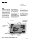
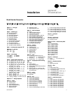
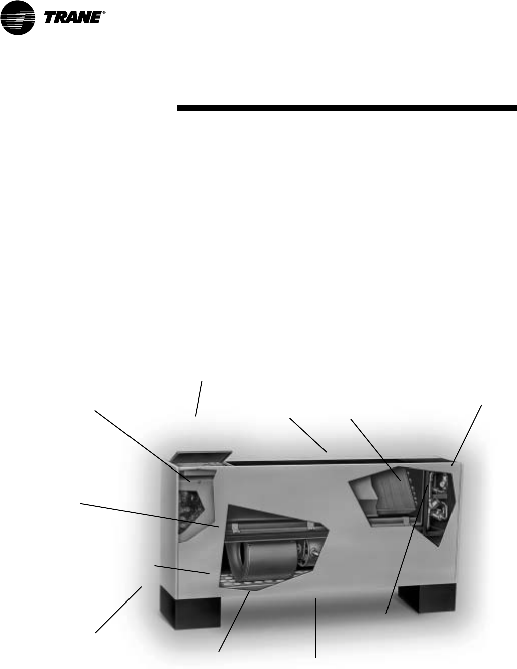
Figure I-GI-1. UniTrane fan-coil unit components. Vertical cabinet model is shown.
General
UniTrane fan-coil and Force Flo units are
intended for single zone applications.
These units have load capabilities of 200
to 1200 cfm. See Figure I-GI-1 for unit
components. Fan-coil units are available
as two-pipe, with or without electric heat
(one hydronic circuit) or four-pipe (two
hydronic circuits). Force-Flo units feature
two-pipe hydronic, electric heat only, or
steam only. Also, these units feature a
variety of factory mounted piping
packages.
Units with the three-speed fan switch
only, are available with the switch
mounted on the unit, or shipped sepa-
rately, to be mounted in the occupied
space. The unit mounted three-speed
general
information
Removable, noncorrosive,
positively-sloped drain pan that’s
easy to clean
Cleanable closed-
cell insulation (non-
fiberglass)
Two, three or
four-row coils
Easy filter access
without front panel
removal
Smaller unit footprint
Easy to remove fan assembly
Quiet operation
16-gage steel construction
Factory assembled,
installed and tested piping
package with IAQ drain pan
to collect condensate
Factory installed
and tested controls
Damper allows up
to 100% fresh air
switch option, can be ordered with a low
voltage(24 volts AC) transformer and
three fan speed relays. The ship seperate
three-speed switch option, only comes
with a low voltage (24 volt AC) trans-
former and three fan speed relays.
The Tracer ZN010, ZN510, and ZN520
controllers are included inside the units
control box assembly. These controllers
utilize analog signals from a unit-mounted
control device or from a control device
mounted in the occupied space.
The controls interface option, includes a
24 volt AC transformer, and an interface
terminal board. Controls provided by an
external source, can be tied into the
interface terminal board, utilizing
1
/
4
"
female spade connectors.
Model Number
Each UniTrane fan-coil and Force-Flo
cabinet heater has a multiple character
model number unique to that particular
unit. To determine a unit’s specific options,
reference the model number on the unit
nameplate on the fan scroll. The unit
nameplate also identifies the serial
number, sales order number, and
installation and operating specifications.
Following is a complete description of the
fan-coil model number. Each digit in the
model number has a corresponding code
that identifies specific unit options.