


46 UNT-SVX07A-EN
pre-startup
requirementsInstallation
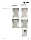
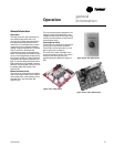
Device Addressing
LonTalk devices are given a unique
address by the manufacturer. This
address is called a Neuron ID. Each Tracer
ZN510 and ZN520 controller can be
identified by its unique Neuron ID, which
is printed on a label on the controller’s
logic board. The Neuron ID is also
displayed when communication is
established using Tracer Summit or
Rover service tool. The Neuron ID format
is 00-01-64-1C-2B-00.
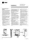
Wire Characteristics
Controller communication-link wiring
must be low capacitance, 18-gage,
shielded, twisted pair with stranded,
tinned-copper conductors. For daisy chain
configurations, limit the wire run length to
5,000 ft. Truck and branch configurations
are significantly shorter. LonTalk wire
length limitations can be extended
through the use of a link repeater.
Recommended
Communication Wiring
Practices
The following guidelines should be
followed while installing communication
wire.
• LonTalk is not polarity sensitive. Trane
recommends that the installer keep
polarity consistent throughout the site.
• Only strip away two-inches maximum of
the outer conductor of shielded cable.
• Make sure that the 24VAC power
supplies are consistent in how they are
grounded. Avoid sharing 24VAC
between LonTalk UCMs.
• Avoid over-tightening cable ties and
other forms of cable wraps. A tight tie
or wrap could damage the wires inside
the cable.
• Do not run LonTalk cable alongside or in
the same conduit as 24VAC power.
• In an open plenum, avoid lighting
ballasts, especially those using 277VAC.
• Do not use a trunk and branch
configuration, if possible. Trunk and
branch configurations shorten the
distance cable can be run.
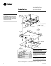
Communication Wiring
Units with Tracer ZN510 and ZN520 Only
Communications
Tracer ZN510 and ZN520 controllers are
LonTalk
®
devices that interface with the
Trane Tracer Summit building
management system. Reference the unit
wiring diagram or submittals.
Ground shields at each Tracer ZN510 and
ZN520, taping the opposite end of each
shield to prevent any connection be-
tween the shield and anther ground.
Refer to Trane publication,
CNT-SVX04A-
EN Installation, Operation and Program-
ming Guide
, for the communication
wiring diagram.
Communication wire must conform to
the following specification:
1. Shielded twisted pair 18 AWG
2. Capacitance 23 (21-25) picofarads (pF)
per foot
3. Listing/Rating – 300V 150C NEC 725-2
(b) Class 2 Type CL2P
4. Trane Part No. 400-20-28 or equivalent,
available through Trane BAS Buying
Group Accessories catalog.
Note: Communication link wiring is a
shielded, twisted pair of wire and must
comply with applicable electrical codes.
Follow these general guidelines when
installing communication wiring on units
with a Tracer ZN510 or ZN520 controller:
• Maintain a maximum 5000 ft.
aggregate run.
• Install all communication wiring in
accordance with the NEC and all local
codes.
• Solder the conductors and insulate
(tape) the joint sufficiently when splicing
communication wire. Do not use wire
nuts to make the splice.
• Do not pass communication wiring
between buildings because the unit will
assume different ground potentials.
• Do not run power in the same conduit or
wire bundle with communication link
wiring.
Note: You do not need to observe polarity
for LonTalk communication links.