


UNT-SVX07A-EN 61
Maintenance diagnostics
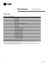
Table M-D-2. Tracer ZN510 controller diagnostics
diagnostic latching? fan valves elec heat damper
auxiliary no enabled no action no action no action
temp. failure
condensate yes off closed off closed
overflow
detection
entering no enabled enabled enabled enabled
water temp.
failure
fan mode no enabled enabled enabled enabled
failure
invalid unit yes disabled disabled disabled disabled
configuration
failure
low temp. yes off open off closed
detection
maintenance yes enabled no action no action no action
required
setpoint no enabled no action no action no action
zone temp. failure no off closed off closed
Notes:
Priority Level: Diagnostics are listed in order from highest to lowest priority. The controller senses and
records each diagnostic independently of other diagnostics. It is possible to have multiple diagnostics
present simultaneously. The diagnostics affect unit operation according to priority level.
Latching: A latching diagnostic requires a manual reset of the controller; while a non-latching diagnostic
automatically resets when the input is present and valid.
Enabled: End device is allowed to run if there is a call for it to run.
Disabled: End device is not allowed to run even if there is a call for it to run.
No Action: The diagnostic has no affect on the end device.
Translating Multiple Diagnostics
The controller senses and records each
diagnostic independently of other
diagnostics. It is possible to have multiple
diagnostics present simultaneously. The
diagnostics are reported in the order they
occur.
Possible diagnostics include:
• Low temperature detection
• Condensate overflow
• Low air flow - fan status
• Discharge air temp limit
• Space temperature failure
1
• Entering water temp failure
1
• Discharge air temp failure
1
• Outdoor air temp failure
1
• Local setpoint failure
1
• Local fan mode failure
1
• CO
2
sensor failure
1
• Generic AIP failure
1
• Humidity input failure
1
• Defrosting compressor lockout
1
• Maintenance required
• Invalid unit configuration
• Generic temperature failure
• Discharge air low limit
1
Non-latching diagnostics automatically
reset when the input is present and valid.
Resetting Diagnostics
There are a number of ways in which
diagnostics are reset:
1. Automatic reset by the controller
2. By initiating a manual output test at the
controller
3. By cycling power to the controller
4. Through Rover™, Trane’s service tool
5. Tracer ZN520: by using any other
communicating device ab le to access
the controller’s diagnostic reset input.
6. Tracer ZN520: by cycling the fan switch
from Off to any speed setting.
Automatic Reset by the Controller
The controller includes an automatic
diagnostic reset function that attempts to
automatically restore the unit when a low
temperature diagnostic occurs.
Note: The controller implements the
automatic diagnostic reset function only
once every 24 hours. For the controller to
increment the 24 hour timer, you must
maintain power to the controller. Cycling
power resets all timers and counters.
After the controller detects the first
special diagnostic, the unit waits 30
minutes before invoking the automatic
diagnostic reset function. The automatic
diagnostic reset function clears the
special diagnostic and attempts to restore
the controller to normal operation. The
controller resumes normal operation until
another diagnostic occurs.
Note: The automatic diagnostic reset
function does not operate during the
manual output test sequence.
If a special diagnostic occurs within 24
hours after an automatic diagnostic reset,
the controller must be manually reset.
Other possible methods of resetting
diagnostics are described in the sections
that follow.
Manual Output Test
To verify proper end device operation,
press the controller’s Test button. This
exercise will verify all outputs in a
predefined sequence, the first of which
will attempt to reset the controller
diagnostics if any are present.
Cycling Power to the Controller
After removing and reapplying the 24
VAC power from the board, the unit
cycles through a power-up sequence. By
default, the controller attempts to reset all
diagnostics present at power-up.
Diagnostics present at power-up and
those that occur after power-up are
handled according to Table M-D-2.
Using Trane’s Service Tool, Rover™
Rover™, Trane’s service tool, can reset
diagnostics present in the controller and
troubleshoot the unit. For more
information, refer to the Trane publication
EMTX-SVX01D-EN
,
Rover Installation,
Operation and Programming Guide
.
Diagnostic Reset
Any device that can communicate the
network variable nviRequest
(enumeration “clear_alarm”) can reset
diagnostics in the Tracer ZN520
controller.The controller also attempts to
reset diagnostics whenever power is
cycled.
Cycling the Fan Switch
Cycle the fan speed switch from Off to
any speed and the controller resets all
diagnostics. Diagnostics may recur
immediately if the problem still exists.