


UNT-SVX07A-EN 51
Operation
sequence of
operation
Sequence of Operation
Tracer ZN010 and ZN510
Note: this section applies only to units
with a Tracer ZN010 or ZN510 controller.
Power-Up Sequence
When 24 VAC power is initially applied to
the Tracer ZN010 or ZN510, the following
sequence occurs:
1. All outputs are controlled off.
2. Tracer ZN010 and ZN510 reads all
input values to detemine initial values.
3. The random start time (0-25 seconds)
expires.
4. Normal operation begins.
Entering Water Temperature Sampling
Function
Both Tracer ZN010 and ZN510 use an
entering water temperature sampling
function to test for the correct water
temperature for the unit operating mode.
For all applications not involving
changeover, the water temperature does
not affect unit operation.
The entering water temperature sam-
pling function opens the main hydronic
valve, waits no more than three minutes
to allow the water temperature to
stabilize, then measures the entering
water temperature to see if the correct
water temperature is available.
The entering water must be five degrees
or more above the space temperature to
allow hydronic heating and five degrees
or more below the space temperature to
allow hydronic cooling.
If the correct water temperature is
available, the unit begins normal heating
or cooling operation. If the measured
entering water temperature is too low or
high, the controller closes the valve and
waits 60 minutes before attempting to
sample the entering water. Reference
Table O-SO-1.
Table O-SO-1. Unit mode as related to water temperature
unit type EWT sensor required? coil water temperature
2-pipe changeover yes COOLS if: space temp - EWT ≥ 5°F
HEATS if: EWT - space temp ≥ 5°F
4-pipe changeover yes COOLS if: space temp - EWT ≥ 5°F
HEATS if: EWT - space temp≥ 5°F
2-pipe heating only no hot water assumed
2-pipe cooling only no cold water assumed
4-pipe heat/cool no cold water assumed in main coil
hot water assumed in aux. coil
Binary Inputs
BIP1: Low Temperature Detection
Option
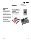
The factory hard wires the low
temperature detection sensor to binary
input #1 (BIP1) on the Tracer ZN010 and
ZN510. The sensor defaults normally
closed (N.C.), and will trip off the unit on a
low temperature diagnostic when
detecting low temperature. In addition,
the Tracer ZN010 and ZN510 control unit
devices as listed below:
fan: off
valves: open
electric heat: off
damper: closed
Note: See the “Diagnostics” section for
more information.
BIP2: Condensate Overflow Detection
Option
The factory hard wires the condensate
overflow sensor to binary input #2 (BIP2)
on the Tracer ZN010 and ZN510. The
sensor defaults normally closed (N.C.),
and will trip off the unit on a condensate
overflow diagnostic if condensate
reaches the trip point. In addition, the
Tracer ZN010 and ZN510 control unit
devices as listed below:
fan: off
valves: closed
electric heat: off
Table O-SO-3. Binary outputs
binary output description pin
BOP1 fan high speed J1-1
BOP2 fan medium speed J1-2
BOP3 fan low speed J1-4
BOP4 main valve J1-5
BOP5 auxiliary valve/electric heat J1-6
BOP6 2-position fresh air damper J1-7
Notes:
1. In a four-pipe application, BOP4 is used for cooling and
BOP5 is used for heating.
2. If no valves are ordered with the unit, the factory default
for the Tracer ZN010 and ZN510 controller are:
BOP4 configured as normally closed
BOP5 configured as normally open
3. If the fresh air damper option is not ordered on the unit,
BOP6 will be configured as none.
Table O-SO-2. Occupancy sensor state table
sensor type sensor position unit occupancy mode
normally open open occupied
normally open closed unoccupied
normally closed open unoccupied
normally closed closed occupied
BIP3: Occupancy Sensor
Binary input #3 (BIP3) on Tracer ZN010
and ZN510 is available for field- wiring an
occupancy sensor, such as a binary
switch or a timeclock, to detect
occupancy. The sensor can be either
normally open or normally closed.
Reference Table O-SO-2.
Binary Outputs
Reference Table O-SO-3 for the Tracer
ZN010 and ZN510’s six binary outputs.