


64 UNT-SVX07A-EN
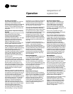
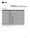
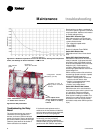
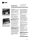
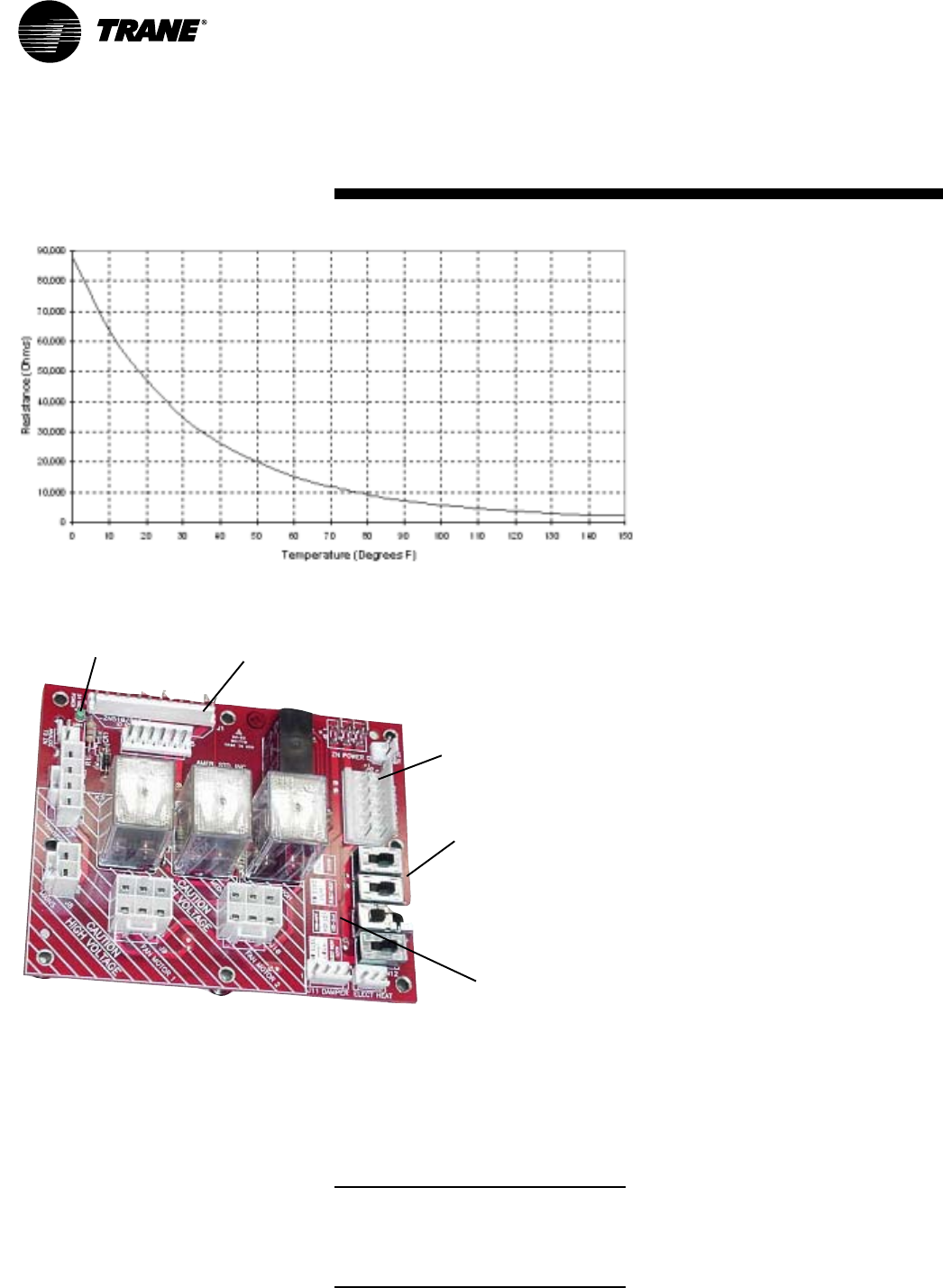
Figure M-T-1. Resistance temperature curve for the zone sensor, entering water temperature
sensor, and discharge air sensor. Thermisitor = 10k
ΩΩ
ΩΩ
Ω
at 77°F.
Maintenance
troubleshooting
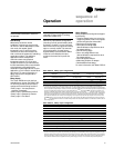
Troubleshooting the Relay
Board
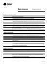
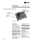
The relay board serves as a common
interface to all of the standard end
devices, and has an LED that indicates
power to the board. Factory switches are
pre-set and locked in place with lock-tight.
However, these seals can be broken if
field-modifications are needed.
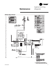
connection to valve &
piping sensor crossover
harness
configuration switches
(factory pre-set)
Note: HAZARDOUS voltage
in dashed area of board!
LED indicates
power
Do not adjust these
switch positions because
it may result in a safety
hazard!
interface to
Tracer ZN controller
Figure M-T-2. Relay board detail
If the board needs replacement, the
switches on the new board must be field-
set in the same positions as the old board,
as shown in the unit wiring diagram.
Note: SW3 and SW4 affect safety
functionality, and they are factory
secured. When replacing a board with
SW3 and SW4, be sure to affix the switch
positions with 3M 3764Q or equivalent.
Board switches are factory set based on
unit control options. Figure M-T-2 shows a
relay board detail. Additional information
on switch settings follows.
Switch SW1: Controller Type
SW1 determines the unit control type.
Position 1 indicates one of the following:
• generic field controller
• low-voltage fan speed switch
• Tracer ZN010
• Tracer ZN510
Position 2 indicates Tracer ZN520.
Switch SW2: Electric Heat
SW2 determines if the unit has electric
heat.
Switch SW3: High-Speed Interlock
SW3 determines if the unit will have a
safety-mandated “high-speed interlock”
with electric heat. High-speed interlock
ensures heat dissipates in a manner that
keeps the unit in a safe operating
condition. SW3 configures the unit to
actuate high-speed interlock if the first or
second stage is on.
SW3 is a three-position slide switch that
actuates high-speed interlock to operate
with specific electric heat coils.
• Position 1: default position and for low
vertical units with electric heat
• Position 2: single-stage electric heat,
model number digit 18 = N
• Position 3: two-stage electric
Switch SW4: Electric Heat Lockout
SW4 allows the unit to use the electric
heat lockout function when hydronic heat
is in operation. Electric heat lockout
prevents electric heat from enabling
when hydronic heating is available. This
feature is on models with both hydronic
and electric heat. Low vertical models
with electric heat, switch SW4 to position
2 (on).