


Verifying operation and communication of the Tracer MP581
BAS-APG001-EN 79
Verifying operation and communication
of the Tracer MP581
This chapter describes the location and function of the Service Pin button
and the light-emitting diodes (LEDs) on the Tracer MP581 controller.
Service Pin button
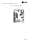
The Service Pin button is located on the main circuit board as shown in
Figure 42. Use the Service Pin button in conjunction with a service tool or
BAS to:
• Identify a device
• Add a device to the active group
• Verify PCMCIA communications
• Make the green Status LED “wink” to verify that the controller is
communicating on the link
Refer to the Rover Operation and Programming guide,
EMTX-SVX01D-EN, for information on how to use the Service Pin button.
Interpreting LEDs
The information in this section will help you interpret LED activity. The
location of each LED is shown in
Figure 42.
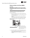
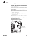
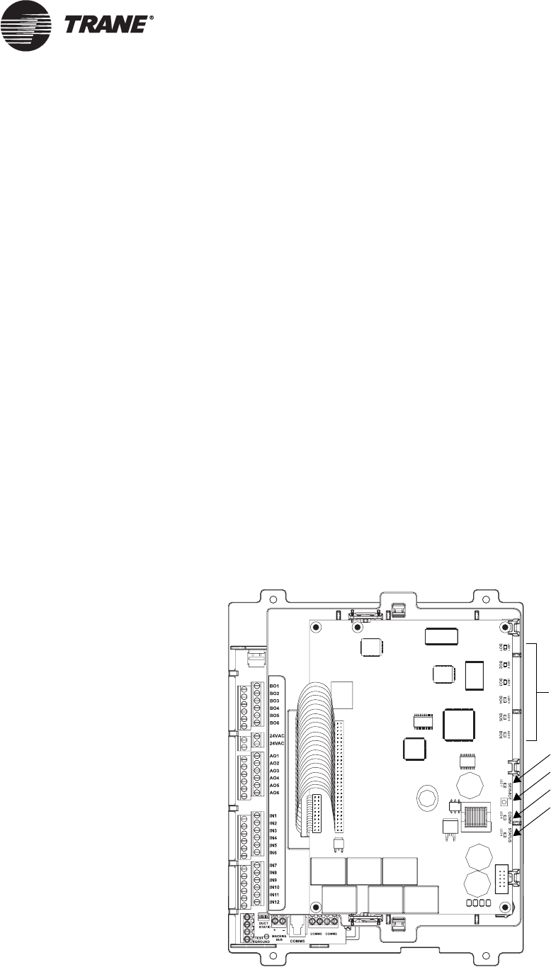
Figure 42. Service Pin button and LED locations
Service Pin button
Service LED (red)
Comm LED (yellow)
Status LED (green)
BO1–BO6 LEDs (green)