


Chapter 6 Installing the EX2 expansion module
96 BAS-APG001-EN
Interpreting EX2 LEDs
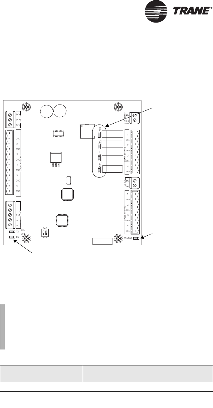
The information in this section will help you interpret LED activity on
the EX2 expansion module.
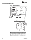
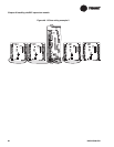
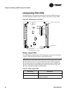
Figure 52 shows the location of each LED.
Figure 52. LED locations on the EX2
Binary output LEDs
The LEDs labeled LD2 through LD5 indicate the status of the four binary
outputs.
Table 24 describes binary output LED activity.
Binary output LEDs
Status LED
TX and RX
communications LEDs
Note:
Each binary output LED reflects the status of the output relay on the
circuit board. It may or may not reflect the status of the equipment
the binary output is controlling. Field wiring determines whether the
state of the binary output LED also applies to the status of the end
device.
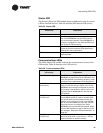
Table 24 describes the LED states.
Table 24. Binary output LEDs
LED activity Explanation
LED is on continuously The relay output is energized.
LED is off continuously The relay output is de-energized or there is no
power to the board.