


Wiring high-voltage ac power
BAS-APG001-EN 59
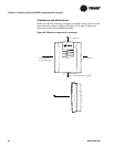
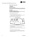
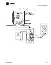
2. Set the enclosure aside and drill holes for the screws at the marked
locations.
Drill holes for #10 (5 mm) screws or #10 wall anchors. Use wall
anchors if the mounting surface is dry wall or masonry.
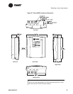
3. Insert wall anchors if needed.
4. Secure the enclosure to the mounting surface with the supplied
#10 (5 mm) screws.
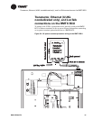
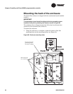
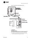
Wiring high-voltage ac power
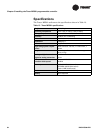
Table 15 lists the available Tracer MP581 model. You can find the model
number on the shipping label or on the product label inside the enclosure.
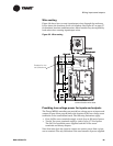
Circuit requirements
To ensure proper operation of the Tracer MP581, install the power supply
circuit in accordance with the following guidelines:
• The Tracer MP581 must receive high-voltage power from a dedicated
power circuit. Failure to comply may cause control malfunctions.
• A disconnect switch for the dedicated power circuit must be near the
controller, within easy reach of the operator, and marked as the dis
-
connecting device for the controller.
• High-voltage power-wire conduits or wire bundles must not contain
input/output wires. Failure to comply may cause the controller to mal
-
function due to electrical noise.
• High-voltage power wiring must comply with the National Electrical
Code (NEC) and applicable local electrical codes.
• High-voltage power wiring requires three-wire 120/230 Vac service.
Use copper conductors only.
Table 15. Tracer MP581 models
Model Number Description
BMTM000DAB00 Tracer MP581 controller, 120 Vac, UUKL
Note:
The voltage utilization range for the Tracer MP581 transformer
is 120 Vac. The panel detects whether the current is 50 or 60
cycle.