


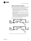
System termination diagrams
BAS-APG001-EN 33
System termination diagrams
System termination diagrams show wire terminations at panels and field
devices. Guidelines for creating system termination diagrams include:
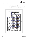
• Diagrams for Tracer MP581 panels may be formatted as lists.
• Diagrams for field devices show: normal state, expected operation,
and voltage requirements. An example of a normal state notation is
normally open. An example of an expected operation description is
closed contact opens damper.
• Diagrams for field devices not furnished by Trane are created during
installation. After installation, the diagrams become part of the as-
built documentation.
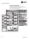
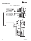
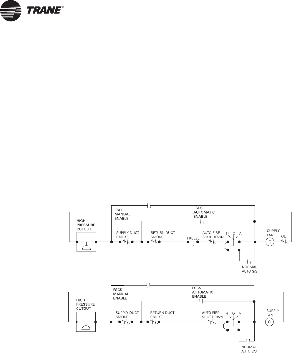
• Diagrams for the control of starters and variable flow devices (VFDs)
must show the required relays and connections for the hierarchy of
control (
Figure 12 on page 33). Relays must enable starters and VFDs
to bypass some safety devices and the local manual switches. Also,
manual controls from the firefighter’s smoke control station (FSCS)
must be wired to give them the highest priority of control.
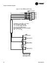
Figure 12. Sample fan starter wiring diagram
Note: Pressure cutouts, duct smoke detectors and auto shutdown are two-pole.