


Chapter 5 Installing the Tracer MP581 programmable controller
66 BAS-APG001-EN
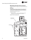
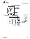
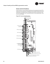
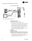
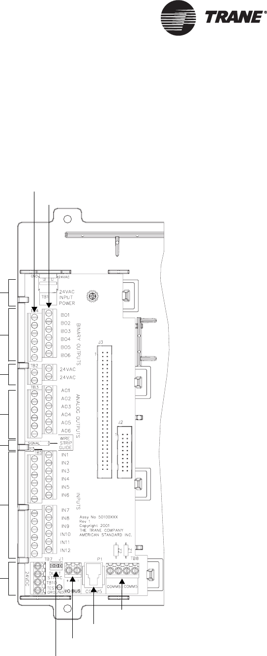
Screw terminal locations
Figure 33 shows screw terminal locations on the termination board. The
top row of screw terminals is for signal wires, and the bottom row of screw
terminals is for common wires. To make sure that the wires lie flat, use
the wire strip guide on the termination board to strip input/output wires
to the correct length.
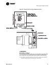
Figure 33. Screw-terminal locations
Binary outputs
Common terminals
Signal terminals
24 Vac power
Analog outputs
Universal inputs
(IN1–IN4 can
accept RTDs)
inputs
Wire strip guide
24 Vdc power
LonTalk screw terminals
LonTalk jack for Rover service tool
I/O bus for EX2 expansion modules
Duct-static pressure connector
24 Vac power
connector