


Mfg No. 164771, Page 9
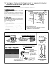
Collar for combustion
air pipe.
Vent Pipe - when a taper-type reducer
is required in the vent pipe; it must be no
more than 6 (152mm) from the box.
Seal the seam in
the vent pipe.
Concentric
Adapter Box
Combustion
air pipe
Field-supplied
mounting brackets
Install seal
in vent pipe
opening
Install the vent pipe
by inserting it into the
terminal side of the
box and pushing it out
through the seal on the
heater side.
NOTE: Be sure flow
direction is correct.
V
ent Flow
Combustion
Air Flow
22"
(559mm)
minimum
Snow
Clearance
6C
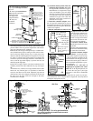
1)Slide combustion
air inlet over the
vent pipe
Install field-supplied
flashing at roof
opening (flashing not
illustrated).
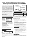
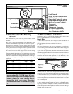
cause the pipe diameter does not change); plus bracket length;
plus the width of the roof; plus the length of the outer inlet air
pipe; plus a minimum of 22" (559mm).
Lubricate the seal and pipe with liquid soap or a rubber lubri-
cant. (Installation Tip: Spray cooking oil works well as a lubri-
cant for this task.) Being sure the pipe is in the proper flow
direction, slide the end through the box and push it out through
the rubber seal. Push evenly using caution not to displace the
seal from its position on the edge of the hole. If the rubber seal
moves, slide the pipe back slightly, re-position the seal, and
slide the pipe through again.
Position the vent pipe so that it will extend a minimum of 22"
(559mm) past the end of the combustion air pipe. See Figure
6B.
A maximum of 6" (152mm) of vent pipe should extend out the
heater side. Any time the pipe is re-positioned, re-check the
seal to be sure that it has not rolled. Adjust the pipe and seal
until the pipe is the correct length on each side of the box and
the seal is over the edge of the hole and tight to the entire
circumference of the pipe.
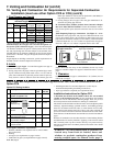
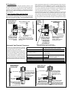
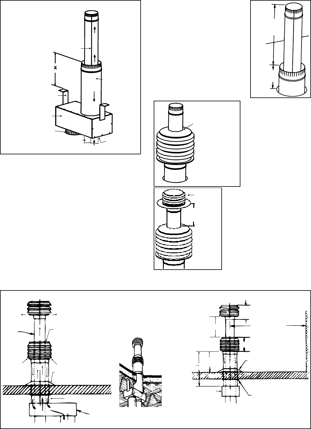
"Through-the-Roof" View of a typical installation
of a vertical vent/inlet air terminal and concentric
adapter (Option CC2)
Flue
Exhaust
(Vent )
Pipe
Vent
Termina
l
Combustion
Air Inlet
Seal with high
temperature silicone
rubber sealant supplied
with the kit.
Flashing
(field supplied)
Roof
Vent
Pipe
Combustion Air Pipe
Concentric
Adapter
9-3/8
(238mm)
12 (305mm)
6 ft (1829mm)
minimum
11 (279mm)
18(457mm)
minimum
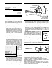
Wall or
Adjoining
Building
Flashing
(field supplied)
Roof
Concentric
Adapter
Thimble
5 ft (1524mm)
maximum (Size
according to
anticipated
snow depth.
Side View
"X" is the length of combustion air
pipe required through and above
the roof
"X" must equal roof thickness
plus clearance required for
anticipated snow
plus ridge and/or
parapet clearance
"X" must not
exceed 60"
(1524mm)
6A
6B
2c) Attach the outside portion of the com-
bustion air pipe to the box. Determine
the length of the combustion air pipe so
that dimension "X" (Figure 6A) is equal
to the roof thickness, plus snow depth
and ridge or parapet clearance, but does
not exceed 60" (1524 mm). Attach the
combustion air pipe to the collar with
sheetmetal screws being careful not to
penetrate the vent pipe.
3. Attach the concentric adapter. Insert
the vent pipe and combustion air pipe up
through the roof and secure the adapter box.
Flash the combustion air pipe to the outside
of the roof as required.
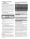
4. Slide the combustion air inlet over the
vent pipe and fasten the collar
to the end of the combustion air
pipe with sheet metal screws
(See Figure 6C). Seal joint at top
between vent pipe and combus-
tion air inlet with silicone seal-
ant to prevent water leakage.
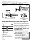
5. Attach the exhaust termi-
nal with sheet metal screws (See
Figure 6D).
6. Vertical vent terminal/combus-
tion air inlet is installed and ready
for connection to the heater.
7. Connect Concentric Adapter
Box to the Heater - Use the pipe speci-
fied and joints required for type of pipe.
If collars at the heater or adapter are dif-
ferent diameters from the pipe (use only
diameters allowed on page 6), make con-
nection with field-supplied taper-type re-
ducer or enlarger.
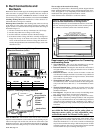
A minimum of 12" (305 mm) of
straight pipe is required at the venter
outlet. Due to the high temperature, do
not enclose the vent pipe or place pipe
closer than 6" (152 mm) to combustible
material.
Installation of the vertical vent and combustion air system on your sepa-
rated-combustion unit is complete. Refer to Figure 6E and verify that all
installation requirements are met.
Exhaust
Terminal
6D
12" (305mm)
minimum
Combustion
Air Inlet
2)Fasten to the end
of the combus-
tion air pipe
3)Seal the top joint
with silicone
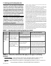
Figure 6E - Installation of Separated-Combustion Unit with Vertical Vent and Combustion Air Pipes (Option CC2)
Rear
View