Mfg No. 164771, Page 3
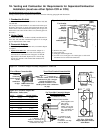
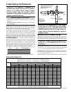
Corner indicators for cutting
inlet air opening
J
2-1/2 (64mm)
2-1/8 (54mm)
16
(406mm)
3-5/8 (92mm)
1 (25mm)
13-1/4
(337mm)
Alternate
Gas
Connection
16
(406mm)
2-1/8 (54mm)
1-1/2 (38mm)
Corner indicators for
cutting inlet air opening
K
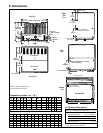
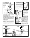
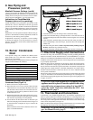
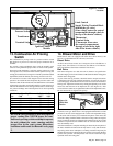
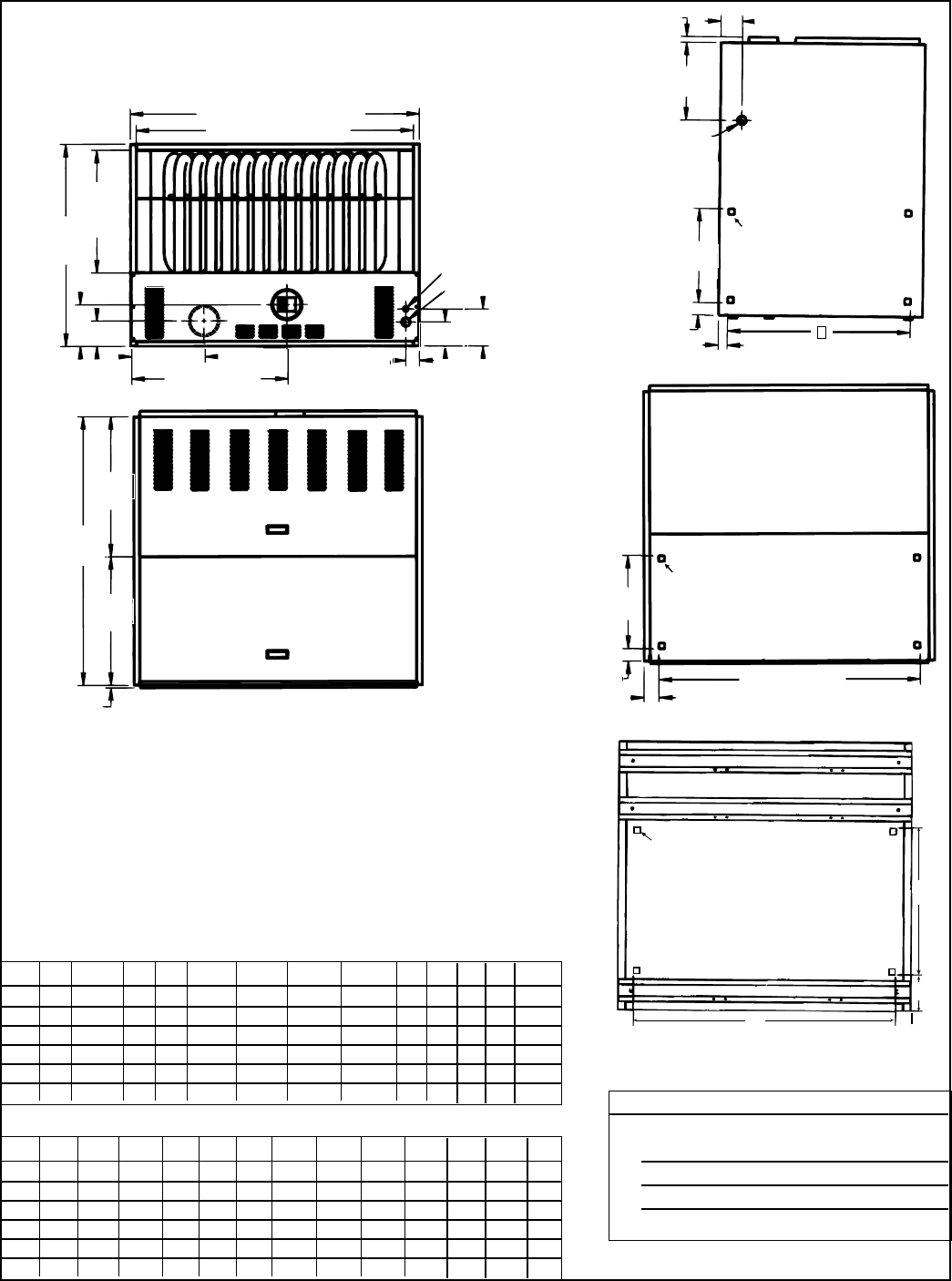
6. Dimensions
Figure 1 - Dimensions of Model CAUA
NOTE: Composite drawings are
not proportional for all sizes.
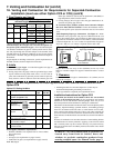
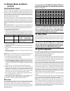
Dimensions (inches + or - 1/8")
Size A B C D E F G H J K M N P
150 38 34-3/4 36 21 7-1/4 3-3/4 12-1/2 24 33 31 19 34 4-5/8
200 38 34-3/4 36 21 7-1/4 3-3/4 12-1/2 24 33 31 19 34 4-5/8
250 50 34-3/4 48 21 7-1/4 4-3/8 12-3/4 27-1/4 45 31 16 46 4-3/4
300 50 34-3/4 48 21 7-1/4 4-3/8 12-3/4 27-1/4 45 31 16 46 4-3/4
350 50 49-3/4 48 34 7 4-3/8 14-1/8 26-3/4 45 44 32 46 4-7/8
400 50 49-3/4 48 34 7 4-3/8 14-1/8 26-3/4 45 44 32 46 4-7/8
Top View
Front View
Right
Side
View
Rear
View
Bottom
View
Dimensions (mm +or- 3)
Size A B C D E F G H J K M N P
150 965 883 914 533 184 95 318 610 838 787 483 864 117
200 965 883 914 533 184 95 318 610 838 787 483 864 117
250 1270 883 1219 533 184 111 324 692 1143 787 406 1168 121
300 1270 883 1219 533 184 111 324 692 1143 787 406 1168 121
350 1270 1238 1219 864 178 111 359 679 1143 1118 813 1168 124
400 1270 1238 1219 864 178 111 359 679 1143 1118 813 1168 124
Air Opening Dimensions
Supply Air (Discharge with duct flange) C x D
Inlet Air Opening (location selected by installer)
Right Side of Heater K x 16" (406mm)
Left Side* of Heater K x 16" (406mm)
Rear of Heater J x 16" (406mm)
Bottom of Heater M x N
*Right side is illustrated; corner indicators for open-
ing are the same on the left side.
A
C Plenum Opening
D
Plenum
Opening
B
E
F
G
H
Electrical
(supply voltage)
Gas
4-1/8
(105mm)
6-3/8
(162mm)
Combustion Air Cutout
150, 200 - 5 (127mm);
250, 300, 350, 400 - 6 (152mm)
Venter Outlet
150, 200, 250 -
5 (127mm);
300, 350, 400 -
6 (152mm)
2-3/8 (60mm)
46-1/2
(1181mm)
24-3/8
(619mm)
22-1/4
(565mm)
1/2 (13mm)
Control Door
Blower Door
BOTTOM VIEW
Corner indicators for
cutting inlet air opening.
Control Side of Hater
M
N
P
2
(51mm)


