


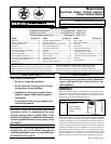
Mfg No. 164771, Page 7
2. Prepare clearance hole through the outside wall for a 6"
diameter pipe (Size 150 or 200) or an 8" diameter pipe
(Size 250, 300, 350, or 400). Outside wall construction
thickness should be between 1" (25mm) minimum and 30"
(762mm) maximum. The larger diameter combustion air
pipe serves as clearance for the exhaust pipe on non-com-
bustible construction. A thimble may or may not be re-
quired depending on wall construction and/or local codes.
3. Prepare the concentric adapter box.
3a) Determine whether field-supplied brackets are
required. The box must be positioned so that the
distance from the outside of the wall to the box is a
minimum of 12" (305mm). Maximum distance is 60"
(1524mm). If brackets are used, box should be angled
slightly to allow for downward pitch of pipes. If used,
attach brackets securely; do not leave any unsealed
holes in the adapter box.
If brackets are not used, when the box is installed,
position it tight against the wall.
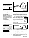
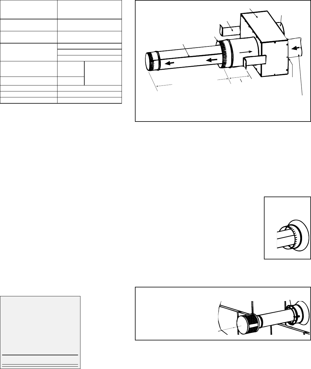
3b) Install the rubber seal and the vent pipe. Locate the
vent pipe opening (no collar) and place the rubber seal
around and over the edge of the metal.
Determine the length of the section of vent pipe by
adding the requirements. On the heater side of all Sizes
except CAUA 250, the vent pipe must extend no more
than 6" (152mm) (length limit does not apply to Size
250 because the pipe diameter does not change); plus
6" (152mm) through the box; plus bracket length; plus
the width of the wall; plus a minimum of 18" (457mm)
on the outside (if
the inlet air pipe
extends recom-
mended 2"
(51mm) beyond
the wall).
Lubricate the seal
and pipe with liq-
uid soap or a rub-
ber lubricant. (In-
stallation Tip:
Spray cooking oil
works well as a lubricant for this task.)
Being sure the pipe is in the proper flow direction,
slide the end through the box and push it out through
the rubber seal. Push evenly using caution not to dis-
place the seal from its position on the edge of the hole.
If the rubber seal moves, slide the pipe back slightly,
re-position the seal, and slide the pipe through again.
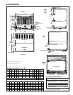
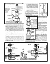
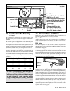
Position the vent pipe so that it will extend a minimum
of 16" past the end of the combustion air pipe. See
2 (51mm)
approx plus
wall thickenss
Vent Pipe - when a taper-type
reducer is required in
the vent pipe; the connection
must be no more than 6
(152mm) from the box.
Seal the seam in the vent pipe.
16 (406mm) minimum
Combustion air pipe
Field-supplied
mounting brackets
Collar for
combustion
air pipe.
Concentric Adapter Box
Install rubber seal in
vent pipe opening.
Vent Flow
Combustion
Air Flow
5A
Figure 5A. On all Sizes except 250, no more than 6" (152mm) of vent pipe
should extend out the heater side. Any time the pipe is re-positioned, re-check
the seal to be sure that it has not rolled. Adjust the pipe and seal until the pipe is
the correct length on each side of the box and the seal is over the edge of the hole
and tight to the entire circumference of the pipe.
3c) Attach the outside portion of the combustion air pipe to the box. Determine
the length by measuring the bracket length (if brackets are used), plus the wall
thickness, plus 2" (51 mm). The inlet pipe should extend beyond the outside
wall approximately 2" (51mm). Attach the inlet air pipe to the collar of the
concentric adapter with sheetmetal screws being careful not to penetrate the
vent pipe.
4. Attach the concentric adapter box to the wall. Insert
the vent pipe and combustion air pipe through the wall.
Push the concentric adapter box flush against the inside
wall or attach to the wall with the field-supplied brackets.
Caulk or flash inlet air pipe on the outside wall. Flashing is
field supplied.
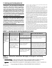
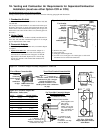
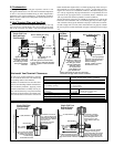
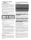
5. Slide the inlet guard over the end of the vent pipe
and position it on the end of the combustion air pipe. See
Figure 5B. Attach the guard to the inlet air pipe with the
four 1/2" lg screws provided.
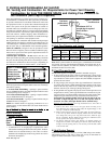
6. Position the vent cap on the end of the vent pipe. Align the cap so that its baffle
strips are positioned on the horizontal and vertical centerlines (See Figure 5C).
Attach the exhaust cap to the vent pipe with sheetmetal screws.
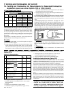
Structure
Forced air inlet within 10 ft
(3.1m)
3 ft (0.9m) above
Combustion air inlet of
another appliance
6 ft (1.8m)
4 ft (1.2m) horizontally
4 ft (1.2m) below
1 ft (30cm) above
Electric meter, gas meter *
and relief equipment
4 ft (1.2m)
horizontally
Gas regulator * 3 ft (0.9m)
Adjoining building or parapet 6 ft (1.8m)
Adjacent public walkways 7 ft (2.1m) above
Grade (ground level) 7 ft (2.1m) above
Minimum Clearances for Vent
Termination Location (all
directions unless specified)
*Do not terminate
the vent directly
above a gas meter
or service regulator.
Door, window, or gravity air
inlet (any building opening)
Flash or caulk
the inlet air pipe
on the outside
wall
5B
IMPORTANT: Install
exhaust cap with baffles
positioned on horizontal and
vertical centerlines as illustrated.
Inlet Air Guard
5C
First, attach the inlet air guard;
Second, attach the exhaust cap
7. Horizontal vent terminal/combustion air inlet Option CC6 is installed and ready
for connection to the heater.
8. Connect the Concentric Adapter Box to the Heater - Use the pipe specified
and joints required for type of pipe. If collar or opening at the heater or adapter are
different diameters from the pipe (use only diameters allowed on page 6), make joint
connection with field-supplied taper-type reducer or enlarger.
A minimum of 12" (305 mm) of straight pipe is required at the venter outlet.
Due to the high temperature, do not enclose the exhaust pipe or place pipe closer
than 6" (152 mm) to combustible material.
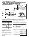
Installation of the horizontal vent and combustion air system on your separated-
combustion unit is complete. Refer to Figure 5D and verify that all installation
requirements are met. Continue to Paragraph 8.
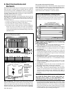
Worksheet - Determine Length of
Vent Pipe through the Box
inches mm
Heater Side (max if + 6 152
diameter changes)
Width of Box + 6 152
Bracket Length + __ ___
Width of Wall + __ ___
Terminal Side (min) + 18 457
Length of Pipe =