


Form 405, Page 8
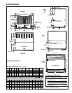
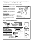
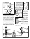
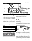
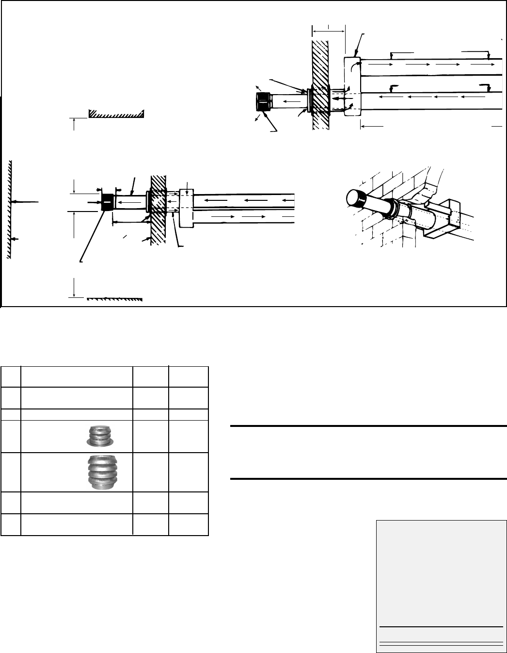
Figure 5D - Installation of a Typical Separated-
Combustion Unit with Horizontal Vent and Combustion
Air Pipes (Option CC6)
Building Overhang
3 ft (914mm)
minimum
6-15/16 (176mm)
Vent Pipe
- PITCH
TO
DRAIN
Adjoining
Building
3 ft (914mm)
minimum
Thimble
Wall
16(406mm)
minimum
24(610mm)
minimum
IMPORTANT NOTE: Exhaust cap must be installed so the baffles
are positioned on horizontal and vertical centerlines.
Building Projection
6ft (1829mm)
minimum
Concentric Adapter Box
Combustion Air Pipe
(PITCH TO DRAIN)
"Through-the-Wall" View of a typical
installation of a horizontal vent/inlet air
terminal and concentric adapter
(Option CC6)
7. Venting and Combustion Air (cont'd)
7A. Venting and Combustion Air Requirements for Separated-Combustion
Installation (must use either Option CC2 or CC6) (cont'd)
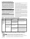
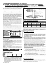
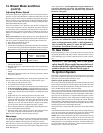
Instructions and Requirements for Installing a
Vertical
Vent Terminal/Combustion Air Inlet
(Requires Concentric Adapter Kit, Option CC2)
Vertical Vent Terminal/Combustion Air Package
(Option CC2) includes:
Field-supplied installation requirements:
• Thimble (a thimble is not required if wall is of non-
combustible construction)
• Flashing
• Vent pipes (see requirements on pages 4 and 6)
• Combustion air pipes (see requirements, pages 4 and 6)
• Mounting brackets for concentric adapter box (or box
may be mounted flush, depending on building construc-
tion)
• Taper-type reducers as required (see requirements on
page 6)
Qty Description 150, 250,300,
200 350,400
1 Complete Vertical Vent Kit 157156 54444
(Same as Option CC2)
1 Concentric Box Assembly 155392 68404
1 Exhaust 155631 53326
Terminal
1 Combustion 155635 53330
Air Inlet
1 Rubber seal for vent pipe 164492 164493
opening in concentric adapter
1 Tube of High Temperature 53335 53335
(450°F) Silicone Sealant
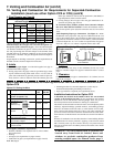
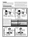
Side View
Screened
Exhaust
Cap
Inlet Air
Guard
Wall
Vent (Flue Exhaust) Pipe
Seal joints; see Require-
ment No. 5 on page 6.
Combustion Air Pipe
Seal Joints
Concentric Adapter
Maximum Length (See Requirement
No. 4 on page 6.)
Minimum length is 5 ft (1.5M)
60 (1524mm) maximum
12 (305mm) minimum
Top
View
Worksheet - Determine Length of
Vent Pipe through the Box
inches mm
Heater Side (max if + 6 152
diameter changes)
Width of Box + 6 152
Bracket Length + __ ___
Width of Roof + __ ___
Inlet Pipe Height + __ ___
Terminal Side (min) + 22 559
Length of Pipe =
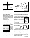
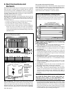
2. Prepare the concentric adapter box.
2a) Determine whether field-supplied brackets are required. If used, attach
brackets securely; do not leave any unsealed holes in the adapter box.
If brackets are not used, when in-
stalled, the box should be tight against
the roof.
2b) Install the rubber seal and the
vent pipe. Locate the vent pipe open-
ing and place the rubber seal around
and over the edge of the metal.
Determine the length of the section of
vent pipe by adding the requirements.
On the heater side of all Sizes except
CAUA 250, the vent pipe must ex-
tend no more than 6" (152mm) (length
limit does not apply to Size 250 be-
Installation Instructions for Option CC2
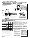
1. Determine the location for the vent terminal on the roof, allowing room for the
concentric adapter box inside. A thimble may or may not be required depending
on building construction and/or local codes. Prepare a hole through the roof for
the combustion air pipe (Sizes 150 and 200, pipe is 6"; Sizes 250-400, pipe is 8").
The air inlet pipe must be flashed or sealed to the roof. Flashing is to be supplied
by the installer as required by roof construction and/or codes.
WARNING: All vent terminals must be positioned or
located away from fresh air intakes, doors and windows to
preclude combustion products from entering occupied
space. See Hazard Levels, Page 2.