


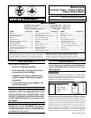
Form 405, Page 6
Instructions and Requirements for Installing
Horizontal
Vent Terminal/Combustion Air Inlet
Option CC6
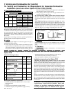
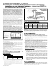
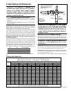
4. Pipe Diameter and Length
Maximum Pipe Length from Heater to Concentric Adapter -
minimum length is five feet (1524mm)
Model Pipe Diameter Maximum 90° Elbow 45° Elbow
CAUA Vent Inlet Air Length Equals* Equals*
150-200 5" 5" 40 ft 5 ft 2.5 ft
12.2 M 1524 mm 762 mm
250 5" 6" 50 ft 5 ft 2.5 ft
15.2 M 1524 mm 762 mm
300-400 6" 6" 50 ft 5 ft 2.5 ft
15.2 M 1524 mm 762 mm
*Reduce maximum length by this amount for each elbow.
7. Venting and Combustion Air (cont'd)
7A. Venting and Combustion Air Requirements for Separated-Combustion
Installation (must use either Option CC2 or CC6) (cont'd)
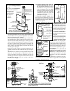
Option CC6 Package includes:
Qty Description 150, 250, 300,
200 350, 400
1 Complete Horizontal Vent Kit 157158 82131
(Same as Option CC6)
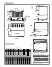
1 Concentric Box Assembly 155392 68404
(See Figures 3A and 3B)
1 Screened 155096 53316
Exhaust Assy
1 Inlet 151755 124940
Guard
4 #10-16x1/2" lg Screws (to 37661 37661
attach the inlet guard)
1 Rubber seal for vent pipe opening 164492 164493
in concentric adapter
1 Tube of high temperature (450°F) 53335 53335
silicone sealant
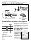
Concentric Pipes (the vent pipe runs concentric through the out-
door portion of the combustion air pipe) - Sizes 150 and 200 require
a 6" diameter combustion air pipe for outdoor portion and a 4" diam-
eter vent pipe through the concentric adapter to the terminal; Sizes
250-400 require an 8" diameter combustion air pipe for the outdoor
portion and a 5" diameter vent pipe through the concentric adapter to
the terminal.
Length depends on building construction; specific requirements are
included with the concentric adapter kit instructions.
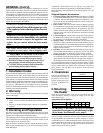
5. Joints
Determined by type of pipe - Provide field-supplied vent pipe as
specified in the Table on page 4.
• If using single wall, 26-gauge or heavier galvanized pipe, secure
slip-fit connections using sheet metal screws or rivets. Seal all
joints. Seal combustion air pipe with pressure sensitive tape ordi-
narily used for warm-air ductwork. Seal flue exhaust pipe with
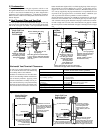
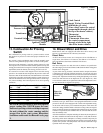
Either collar
or smaller
diameter pipe
Taper-type Connector
Secure joints with sheetmetal
screws and seal.
Field-supplied installation requirements:
• Thimble (a thimble is not required if wall is of non-combus-
tible construction)
• Flashing
• Vent pipes (see requirements on pages 4 and 6)
• Combustion air pipes (see requirements on pages 4 and 6)
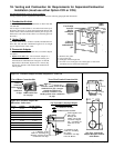
Installation Instructions for Option CC6
1. Determine the location on the outside wall for the vent terminal
(Applies to all horizontal vent kits). In most applications, the terminal
would be on a level with the heater mounting height. Allow 1/4" per foot
downward pitch toward the terminal for draining of condensation.
The distance of the termination of the horizontal vent from adjacent public
walkways, adjacent buildings, openable windows, and building openings
must be in accordance with local codes or, in the absence of local codes,
must conform with National Fuel Gas Code. Local codes supersede all
provisions in these instructions and in the National Fuel Gas Code. Mini-
mum clearances for the horizontal vent terminal are as shown in the table on
page 7.
Products of combustion can cause discoloration of some building finishes
and deterioration of masonry materials. Applying a clear silicone sealant
that is normally used to protect concrete driveways can protect masonry
materials. If discoloration is an esthetic problem, relocate the vent or install
a vertical vent.
WARNING: All vent terminals must be positioned or
located away from fresh air intakes, doors and
windows to preclude combustion products from
entering occupied space. See Hazard Levels, page 2.
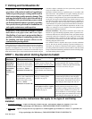
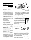
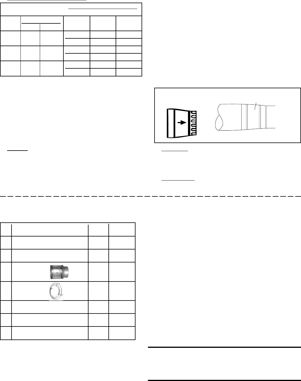
Reducer
Airflow
Figure 4 - When joining different pipe diameters, use taper-
type pipe connectors
either tape suitable for 550°F (such as Option FA1, P/N 98266) or
high-temperature (450°F) silicone sealant.
• If using Category III vent pipe, follow the pipe manufacturer's in-
structions for joining pipe sections.
In Concentric Pipes (outdoor portion) from Concentric Adapter
Box to Air Inlet and Vent Terminal - Follow the installation instruc-
tions for the specific option (CC6 for horizontal vent; CC2 for vertical
vent).
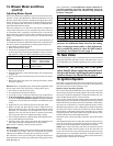
Joints Requiring Taper-type Connections (See Figure 4) - When
the diameter of the pipe in the vent pipe run is different from the vent
pipe in the terminal section, the joint must be made with a taper-type
pipe connector. Install the connector no more than 6" (152mm) from the
concentric adapter box. A 5" to 4" reducer is required in the vent pipe on
Sizes 150 - 200; a 6" to 5" reducer is required on Sizes 300 - 400.
6. Support
Support horizontal runs every six feet (1829mm); do not rely on the
heater or concentric adapter for support of either horizontal or vertical
pipes.
7. Clearance
Clearance from the vent pipe to combustibles is 6" (152mm). Do not
enclose the vent pipe.
• Mounting brackets for concentric adapter box (or box may be
mounted flush, depending on building construction)
• Taper-type reducers as required (see requirements above)