


Mfg No. 164771, Page 15
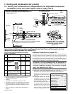
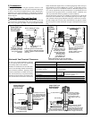
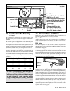
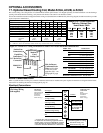
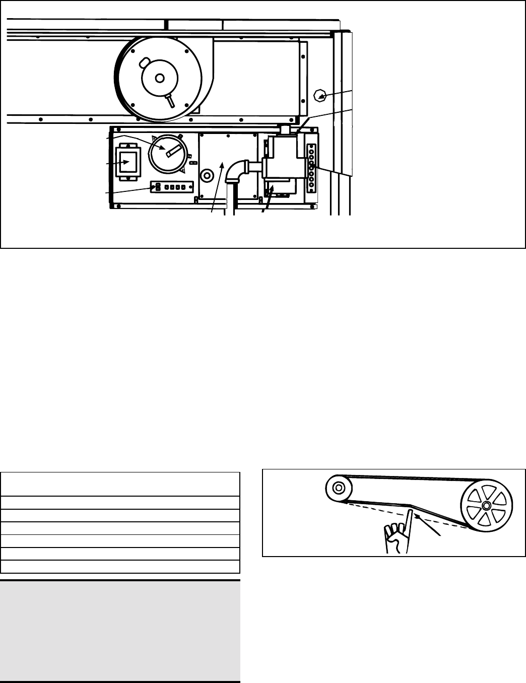
Limit Control
Supply Wiring Terminal Block
(behind the gas valve)
(Line voltage enters the control
compartment through a hole in
the top of the heater cabinet.)
Thermostat
Terminal Strip
(Thermostat wires enter
the control compartment
through a hole in the right
side of the heater cabinet.)
Contactors
Gas
Valve
Ignition Control
Module
Terminal Strip
Transformer
Pressure Switch
Venter
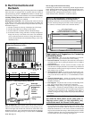
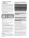
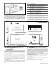
3/4 (19mm)
Figure 16 -
Check Belt
Tension
Figure 15 - Control
Locations
14. Blower Motor and Drive
Model CAUA units are equipped with either direct drive motor(s) and
blower(s) or adjustable belt-drive blower(s) and motor.
Direct Drive
All direct drive blower motors are 1 horsepower. Sizes 150-200 have a
single motor. Size 150 has a 12-9 blower; Size 200 has a 12-12 blower.
Sizes 250-400 have dual motors with dual 12-9 blowers.
Belt Drive
The motor horsepower on a belt drive unit is whatever was specified on
the order ranging in size from 1/4 HP to 5 HP. Check the heater rating plate
and the motor rating plate.
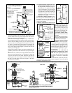
As part of the start-up procedure, check belt tension. Proper belt tension
is important to the long life of the belt and motor. A loose belt will cause
wear and slippage. Too much tension will cause excessive motor and blower
bearing wear. Adjust the belt tension by turning the adjusting screw on the
motor base until the belt can be depressed 3/4". (See Figure 16.) After
correct tension is achieved, re-tighten the locknut on the adjustment screw.
Be sure that the belt is aligned in the pulleys.
13. Combustion Air Proving
Switch
The combustion air proving switch is a pressure sensitive switch
that monitors air pressure to ensure that proper combustion air is
available.
The switch is single pole/double throw with the normally open
contacts closing when the proper airflow is sensed in the system.
On start-up when the heater is cold, the sensing pressure is at the
most negative level, and as the heater and flue system warm up, the
sensing pressure becomes less negative. After the system has reached
equilibrium (about 20 minutes), the sensing pressure levels off.
If a restriction or excessive flue length or turns cause the sensing
pressure to be outside the switch setpoint, the pressure switch will
function to shut off the main burners. The main burners will remain
off until the system has cooled and/or the flue system resistance is
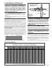
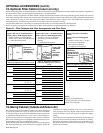
reduced. The table below lists the approximate water column nega-
tive pressure readings and switch setpoints for sea level operating
conditions.
Model Start-Up Equilibrium Set Point Set Point
Size Cold “OFF”“ON”
150 1.45 1.05 .75 .90
200 1.50 1.05 .75 .90
250 1.55 1.10 .75 .90
300 1.60 1.15 .75 .90
350 1.30 1.05 .75 .90
400 1.20 1.00 .75 .90
DANGER: Safe operation of this unit requires
proper venting flow. NEVER bypass the com-
bustion air proving switch or attempt to operate
the unit without the venter running and the
proper flow in the vent system. Hazardous
conditions could result. See Hazard Levels, page
2.
Most blower motors are equipped with thermal overload protection of the
automatic, reset type. If the motor is not equipped with thermal overload
protection, the unit will be equipped with a starter. The adjustable setting
on the starter will be factory set to match the amp draw of the motor and
sealed. No change should be made to the starter setting unless the original
motor is replaced. Starters are equipped with a manual reset. If an overload
condition is experienced, the condition must be corrected and the starter
must be manually reset.
After the installation is complete including all ductwork, the amp draw of
the motor should be checked with an amp meter to verify that the motor
amp rating on the motor nameplate is not being exceeded. Amps may be
adjusted downward by reducing the blower speed or by increasing the duct
system static pressure. The temperature rise must be within the range
specified on the unit rating plate.