


Form 405, Page 4
7. Venting and Combustion Air
WARNING: The vent must be installed in
accordance with national and local regulations.
Failure to provide proper venting could result in
death, serious injury and/or property damage. This
unit must be installed with a vent to the outside of
the building. Safe operation of any power-vented
gas-fired equipment requires a properly operating
vent system, correct provision for combustion air,
and regular maintenance and inspection.
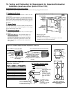
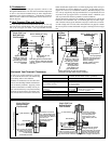
WARNING: Units installed in multiples require
individual vent pipe runs and vent caps.
Manifolding of vent runs is not permitted due to
possible recirculation of combustion products into
the building and back pressure effects on the
combustion air proving switch.
Venting must be in accordance with the National Fuel Gas Code Z223.1
or CAN/CGA B149.1 and B149.2, Installation Code for Gas Burning
Appliances and Equipment, and all local codes. Local requirements
supersede national requirements. Combustion air for this heater may be
either taken from the space or may be ducted from the outside using the
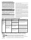
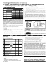
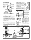
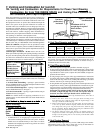
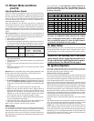
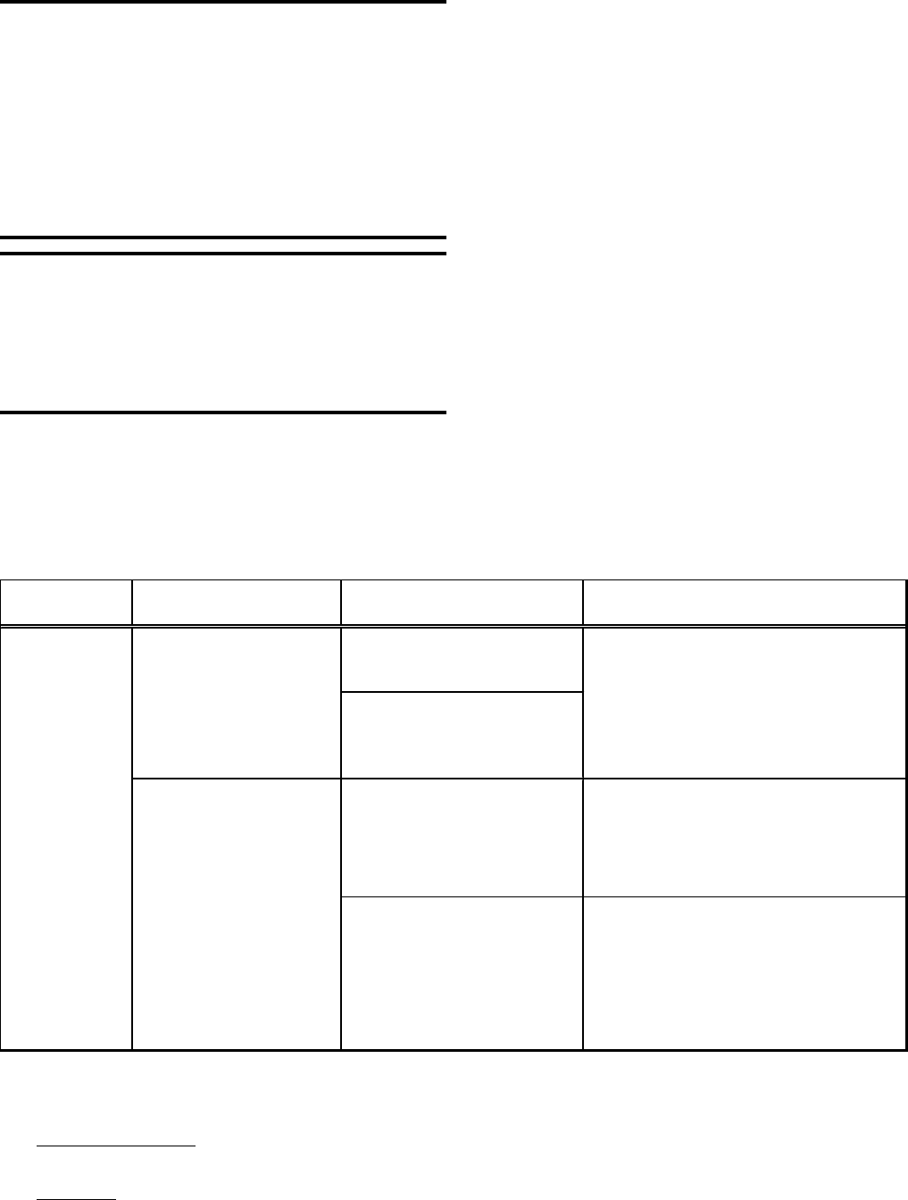
STEP 1 - Decide which Venting System to Install:
concentric adapter combustion air/vent system. Flue products must
always be vented to the outdoors.
Installation should be done by a qualified agency in accordance with
these instructions. The qualified service agency installing the vent or
vent/combustion air system is responsible for the installation.
The venting or venting/combustion air systems illustrated in this manual
are the only ones approved for a Model CAUA heater. However, since
more than one system is approved and requirements vary depending on
the type of installation, the first step must be deciding which vent or
vent/combustion air system is going to be installed. Review the follow-
ing matrix of vent types and installation requirements. If there is any
doubt as to what type of vent is required, contact the equipment dis-
tributor before beginning installation.
Hazards of Chlorines - The presence of chlorine vapors in the com-
bustion air of gas-fired heating equipment presents a potential corro-
sion hazard. Chlorine will, when exposed to flame, precipitate from the
compound, usually freon or degreaser vapors, and go into solution with
any condensation that is present in the heat exchanger or associated
parts. The result is hydrochloric acid which readily attacks all metals
including 300 grade stainless steel.
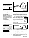
Care should be taken to separate these vapors from the combustion
process. This may be done by installing a separated combustion sys-
tem and/or wise location of the furnace with regard to exhausters or
prevailing wind direction. Chlorine is heavier than air. This fact should
be kept in mind when determining installation locations of heating equip-
ment and building exhaust systems.
Type of
Installation
Type of Vent System
(Description/Instructions)
Vent Configuration/Options
Required
Type of VENT Pipe* Required
Horizontal Vent / Option CC6
(includes concentric adapter box,
exhaust terminal, and inlet air guard)
Vertical Vent / Option CC2
(includes concentric adapter box,
exhaust terminal, and combustion air
inlet)
Horizontal Vent / Option CC1
Vent Cap or field-supplied
equivalent (see page 11)
Use either vent pipe approved for a Category III
appliance OR appropriately sealed 26-gauge
galvanized steel or equivalent single-wall pipe. If
local code requires, the terminal section may be
double-wall pipe with a single-wall vent run.
Vent pipe listed above for a horizontal power-
vented system may be used, OR vent pipe
approved for a Category I heater may be used.
Single-wall pipe or double-wall (Type B) vent
pipe are suitable for use with a Category I heater.
If local code requires, the terminal section may be
double-wall pipe with a single-wall vent run.
Use either vent pipe approved for a Category III
appliance OR single-wall, 26-gauge or heavier
galvanized (or a material of equivalent durability
and corrosion resistance) vent pipe.
Power-Vented
(uses a power
venter to draw combustion air
from the indoor space and
exhaust flue products to the
outdoors) -
(follow
Instructions in S ection 7B)
COMMERCIAL/
INDUS TRIAL
(Harmonized
ANSI Z83.8-1996
and Canadian
Standard
CAN/CGA 2.6-
M96)
S eparated-Combustion
(uses a power venter to duct
combustion air from outdoors
and exhaust flue products to
the outdoors) -
(follow
Instructions in S ection 7A)
At least 1/2 of the Equivalent
Vent Length is Vertical / Option
CC1
Vent Cap or field-supplied
equivalent (see page 11)
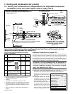
STEP 2 - Follow the instructions that apply to the type of vent being
installed
• Separated-Combustion -- requires air inlet pipe, exhaust vent pipe, and concentric adapter kit (Option CC2 or CC6)
Using required pipe (See Table above), FOLLOW INSTRUCTIONS IN SECTION 7A
• Power Vent -- requires vent pipe and vent cap (Option CC1 or field-supplied Type L Breidert Air-x-hauster
®
or equivalent vent
cap)
Using required pipe (See Table above), FOLLOW INSTRUCTIONS IN SECTION 7B