


Form 405, Page 14
3
4
2
1
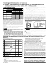
(supply) pressure must be within the specified range for the
gas being used both when the heater is in operation and on
standby. Incorrect inlet pressure could cause excessive mani-
fold gas pressure immediately or at some future time.
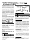
Instructions to Check Manifold
Pressure (when unit is operating):
1) With the manual valve positioned to prevent flow to the
main burners, connect a manometer to the 1/8" pipe outlet
pressure tap in the valve. NOTE: A manometer (fluid-filled
gauge) is recommended rather than a spring type gauge due
to the difficulty of maintaining calibration of a spring type
gauge.
2) Open the valve and operate the heater. Measure the gas
pressure to the manifold. Normally adjustments should not
be necessary to the factory preset regulator.
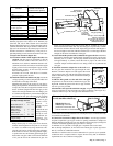
If adjustment is necessary, set pressure to correct settings
by turning the regulator screw IN (clockwise) to increase
pressure. Turn regulator screw OUT (counterclockwise) to
decrease pressure.
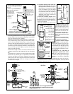
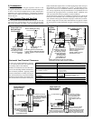
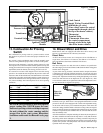
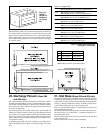
1) Assemble the brass nut, the sealing washer, and the 90° fitting.
2) Position the threaded fitting up through the hole so that the hose barb is
toward the bushing in the side of the cabinet. Attach using the silver-colored
locknut.
3) Under the burner, push the tubing onto the hose barb, being sure that it is
secure. Maintaining a downward slope, extend the hose out through the
cabinet side.
4) Just after exiting the cabinet, create a trap in the line by making a loop in
the hose. Secure the loop with the wire ties.
5) Continue downward with the tubing, connecting it into the coil drain pipe.
Figure 14 - Burner Condensate Drain Connection
10. Burner Condensate
Drain
If an optional cooling coil is installed on a Model CAUA
heater (either now or at a later time), a burner condensate
drain line must be installed.
The following parts to install the drain line are packaged and
shipped with all Model CAUA heaters.
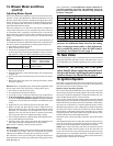
Qty P/N Description
1 165955 6-ft length of 3/8" I.D. Tubing
1 165952 90° Nylon Fitting, 1/4" NPT x 3/8"
tubing
1 110628 1/4" NPT Brass Nut
1 171527 1/4" Locknut, Hex, T& B 139
1 165953 Sealing Washer
2 20913 Nylon Wire Ties, T&B #TY-24M
1 87556 Snap Bushing, Heyco SB 625-8
Instructions for Installing the Burner
Condensate Drain (Figure 14)
1. Remove the burner compartment door.
2. The burner box cover is in two sections. On the left side
of the burner box cover, disconnect the flame sensor wire
and the flame rollout switch wires. Disconnect the sili-
cone tubing from the static tap. Remove the left section
of the burner box cover.
3. Determine which side of the cabinet will be most conve-
nient for the drain line. Remove the hole plug on that side
and insert the snap bushing from the package.
4. Locate the hole in the bottom center of the burner pan
and remove the plug. Follow the instructions in Figure 14
to install the drain. Complete all steps as listed in the
illustration.
When installation of the burner condensate drain is com-
plete, re-assemble the heater.
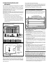
11. Electrical Supply and Connections
All electrical wiring and connections, including electrical grounding, MUST be
made in accordance with the National Electric Code ANSI/NFPA No. 70 (latest
edition) or, in Canada, the Canadian Electrical Code, Part I-C.S.A. Standard C22.1.
In addition, the installer should be aware of and comply with any local ordinances
or gas company requirements.
Check the rating plate on the heater for the supply voltage and current require-
ments. A separate line voltage supply with fused disconnect switch should be run
directly from the main electrical panel to the heater. All external wiring must be
within approved conduit and have a minimum temperature rise rating of 60°C.
Conduit from the disconnect switch must be run so as not to interfere with the
service panels of the heater.
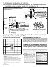
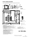
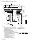
The electrical supply and control wiring enter at the top of the heater (See Figure
1, page 3) and connect to the terminal strip behind the gas valve (See Figure 15).
Consult the wiring diagram supplied with your heater. Typical wiring diagrams are
on pages 17 and 18.
CAUTION: If any of the original wire as supplied with the
appliance must be replaced, it must be replaced with wiring
material having a temperature rating of at least 105°C,
except for sensor lead wires which must be 150°C. See
Hazard Levels, page 2.
12. Thermostat and Connections
A thermostat is not standard equipment but is an installation requirement. Use
either an optional thermostat available with the heater or a field-supplied 24-volt
thermostat. Install according to the thermostat manufacturer's instructions. Con-
trol wiring enters on the right side of the heater and connects to the terminal strip
in the control compartment; see Figure 15.
Make sure that the heat anticipator setting on the thermostat is in accordance with
the amperage value noted on the wiring diagram of your heater.
WARNING: If you turn off the power supply, turn off the
gas. See Hazard Levels, page 2.
!!
!!
! Hex Locknut (silver)
—Burner Bottom Pan—
""
""
" Sealing Washer
##
##
# Brass Nut
$$
$$
$ 90° Nylon Fitting
9. Gas Piping and
Pressures (cont'd)
Manifold Pressure Settings (cont'd)