


Mfg No. 164771, Page 19
17. Optional Cased Cooling Coil, Model ACUA, ACUB, or ACUC
This cased cooling coil is designed for use with the Model CAUA upflow heater. It is shipped separately for field installation over the discharge
opening of the heater. Before installing, verify that the coil cabinet is the same size as the heater cabinet.
Follow the installation instructions shipped with the cooling coil (Installation Form RZ 405-CC), the wiring diagram, and the instructions provided
by the compressor manufacturer.
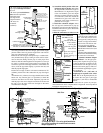
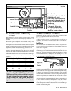
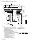
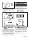
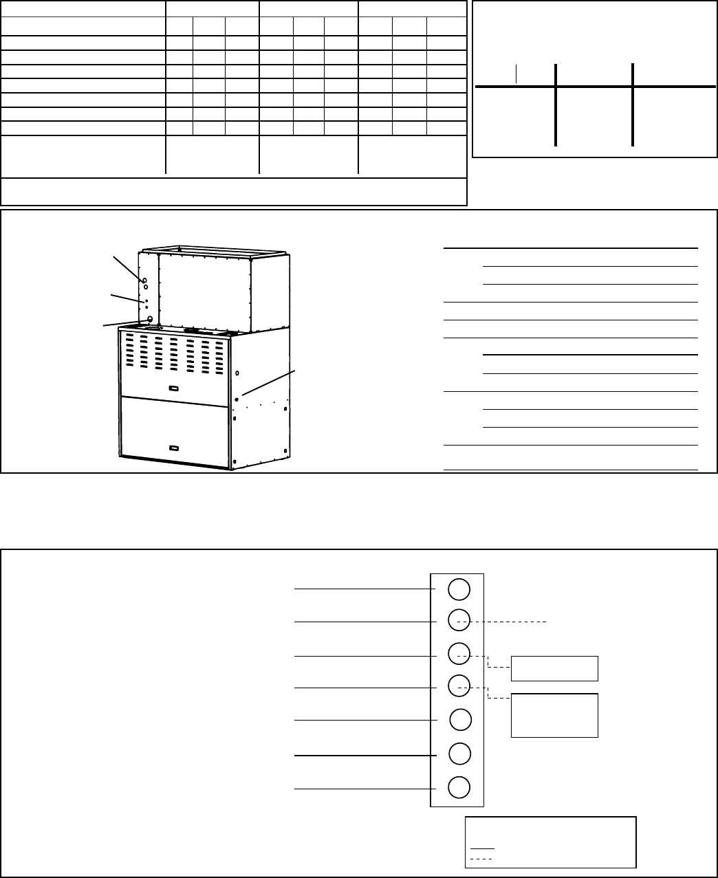
Figure 19 - A Model ACU cooling coil installed on a Model CAUA heater and the line connection sizes
Model CAUA
Heater
Model ACU
Cased
Cooling Coil
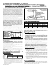
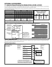
Model ACUA ACUB ACUC
Size 060 072 090 090 120 150 120 150 180
Nominal Cooling Capacity (MBH) 60 72 90 90 120 150 120 150 180
Refrigerant Type R-22 R-22 R-22 R-22 R-22 R-22 R-22 R-22 R-22
Thermal Expansion Valves* 1 1 1 1 2 2 2 2 2
Approximate Weight (lbs) 83 86 105 110 122 140 176 180 188
No. of Intertwining Circuits 8 8 12 12 12 18 12 16 18
Face Area (sq ft) 7.79 7.79 9.38 14.04 11.67 13.70 17.13 15.38 17.13
Rows-Fins/Inch 2-10 2-12 3-10 2-12 3-10 3-12 2-12 3-10 3-10
Airflow (cfm) Low 1800 3000 4000
Nominal 2400 4000 5000
High 3000** 5000** 6000**
* - TXV's are factory supplied. Models with two TXV's have intertwined circuiting.
** - Airflow in excess of maximum values shown may result in blow-off of condensation.
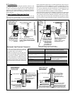
Heater/Coil Cross-Reference
Table by Cabinet Size
Heater Model CAUA
150 200 250 300 350 400
ACUA ACUB ACUC
060 090 120
072 120 150
090 150 180
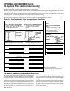
Burner Condensate Drain
When a system includes a cooling coil, a burner condensate drain must be installed. The parts required for the drain are shipped with the heater.
Instructions for installing the drain are in Paragraph 10, page 14.
Electrical Connections
Model Size Connections
ACUA 060/072 (1) 7/8" Suction Line
060 (1) 3/8" Liquid Line
072 (1) 1/2" Liquid Line
090 (2) 7/8" Suction Lines
090 (2) 3/8" Liquid Lines
ACUB 090/120/150 (2) 7/8" Suction Lines
090/120 (2) 3/8" Liquid Lines
150 (2) 1/2" Liquid Lines
ACUC 120/150/180 (2) 7/8" Suction Lines
120 (2) 3/8" Liquid Lines
150/180 (2) 1/2" Liquid Lines
Drain line connection is 3/4" for all sizes.
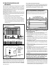
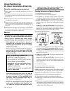
R
C
Y
1
Y
2
W
1
W
2
G
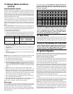
Thermostat
Connections
(Read thermostat
manufacturers
installation
instructions
before wiring.)
24V Supply *
Common
1st Stage Cooling
2nd Stage Cooling
1st Stage Heating
Optional 2-Stage Heating
Fan
Heater Terminal Strip
Common
1st stage cooling
24V control relay
2nd stage cooling
24V control relay
for Sizes 090, 120,
150, and 180
Condensing Unit
Connections
(Read
manufacturers
installation
instructions
before wiring.)
* A separate 24V control transformer may
be required for the condensing equipment controls
Install a jumper wire between RH and RC terminals
on the thermostat for single transformer operation.
Consult the thermostat manufacturers instructions.
Legend (field-supplied 24V wiring)
Thermostat wiring - 24V
Field control wiring - 24V
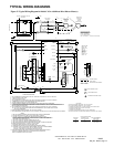
Figure 20 - Typical
Low Voltage Wiring
(field-supplied)
Suction Line
Connection(s)
3/4" Drain Line
Connection
Liquid Line
Connection(s)
Hole for Burner
Condensate Drain
Tube (use this hole
or the one on the
opposite side) - see
Paragraph 10, page
14
OPTIONAL ACCESSORIES