


Form 405, Page 20
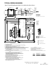
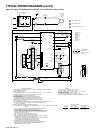
OPTIONAL ACCESSORIES (cont'd)
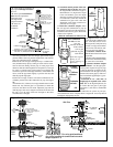
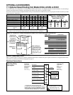
18. Optional Filter Cabinet (return air only)
A filter cabinet designed for 2" pleated disposable or permanent metal filters is shipped separately for field assembly and installation. Depending on
the option selected, filters are either shipped with the cabinet or are field-supplied.
To adapt to a variety of applications, the heater cabinet is designed so that the filter cabinet can attach on either the right side, the left side, or the rear
of the heater. The larger filter cabinets (left two tables below) are uniquely designed so that the same cabinet can be field-assembled and installed with
either a horizontal or vertical air inlet. The smaller filter cabinet in the table on the right is limited to Sizes 150 and 200 and is available with a
horizontal inlet only. All cabinets have door panels for easy filter removal for changing or cleaning.
All of the filter cabinets have a duct flange for attaching the inlet air duct. For inlet duct dimensions, see Paragraph 8.
Follow the step-by-step instructions included with the filter cabinet package to assemble and attach it to the heater.
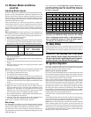
Figure 21 - Filter Cabinets with Filter Arrangements and Filter Sizes
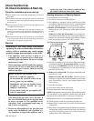
Sizes of Permanent or Pleated 2"
Filters for Options CW4, CW5, or CW6
Size CFM FPM Filters
150 1800 281 (4) 16 x 16
2400 375 (4) 16 x 16
3000 469 (4) 16 x 16
200 2400 375 (4) 16 x 16
3000 469 (4) 16 x 16
250 3000 469 (4) 16 x 16
*4000 625 (4) 16 x 16
**5000 781 (4) 16 x 16
(4) 16 x 16
300 3000 469 (4) 16 x 16
*4000 625 (4) 16 x 16
**5000 781 (4) 16 x 16
(4) 16 x 16
350 4300 448 (6) 16 x 16
5000 521 (6) 16 x 16
*6000 625 (6) 16 x 16
400 4300 448 (6) 16 x 16
5000 521 (6) 16 x 16
*6000 625 (6) 16 x 16
NOTES:
* Requires 2" permanent filters.
** If using side inlets, two cabinets must be
installed, one on each side.
Sizes of Permanent or Pleated 2"
Filters for Options CW7, CW12, or
CW11
Size CFM FPM Filters
150 1800 281 (4) 16 x 16
2400 375 (4) 16 x 16
3000 469 (4) 16 x 16
200 2400 375 (4) 16 x 16
3000 469 (4) 16 x 16
250 3000 313 (6) 16 x 16
4000 417 (6) 16 x 16
5000 521 (6) 16 x 16
300 3000 313 (6) 16 x 16
4000 417 (6) 16 x 16
5000 521 (6) 16 x 16
350 4300 448 (6) 16 x 16
5000 521 (6) 16 x 16
*6000 625 (6) 16 x 16
400 4300 448 (6) 16 x 16
5000 521 (6) 16 x 16
*6000 625 (6) 16 x 16
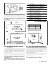
Option CW4 with 2" Pleated Filters
Option CW5 with 2" Permanent Filters
Option CW6 for Field-Supplied Filters
• Attaches on Either Side of the Heater
• Vertical (Top) or Horizontal Inlet Opening
• "V" Filter Rack Arrangement
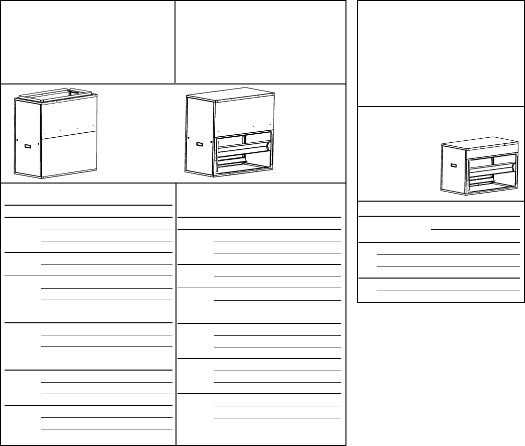
Filters for Options CW8, CW9, CW10
SizeCFM FPM 2" Filters
Pleated Permanent
150 1800 375 (2) 12 x 32 (4) 12 x 16
2400 500 (2) 12 x 32 (4) 12 x 16
*3000 625 -- (4) 12 x 16
200 2400 500 (2) 12 x 32 (4) 12 x 16
*3000 625 -- (4) 12 x 16
Figure 21A -
Assembled with
Vertical Air
Inlet Opening
Figure 21B -
Assembled
with
Horizontal
Air Inlet
Opening
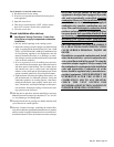
Figure 21C -
Small Filter
Cabinet for Sizes
150 and 200 only
-- Horizontal Air
Inlet Only
Option CW7 with 2" Pleated Filters
Option CW12 with 2" Permanent Filters
Option CW11 for Field-Supplied Filters
• Attaches on the Rear of the Heater
• Vertical (Top) or Horizontal Inlet
Opening
• "V" Filter Rack Arrangement
Option CW8 with 2" Pleated Filters
Option CW9 with 2" Permanent
Filters
Option CW10 for Field-Supplied
Filters
• Attaches on either Side or the Rear
of a Size 150 or 200 Heater
• Horizontal Inlet Opening
• "V" Filter Rack Arrangement
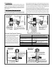
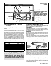
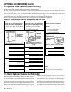
19. Mixing Cabinet (Outside and Return Air)
The optional mixing box for the Reznor
®
Model CAUA heater is designed
to provide the system with a supply air mixture of return air and outside
air. Any percentage of outside air can be supplied to the unit as long as the
air temperature entering the blower is 35°F or above. The mixing box is
available in an assortment of configurations with a selection of actuators
and controls. All mixing boxes are completely assembled at the factory for
field attachment to the rear of a Model CAUA heater.
Follow the instructions packed with the mixing box to cut out the opening
and attach the mixing box. If the mixing box has dampers, follow the
instructions for routing the damper motor wires, and connect the
wires according to the wiring diagram. If there are both return air and
outside air dampers, follow the directions to adjust the damper
linkage.
All mixing box inlet air openings have duct flanges for attachment of
ductwork. Ductwork must be attached to the outside air opening.
Removable door panels provide for filter access from either end of
the cabinet. If the box was ordered with optional filters, it is shipped
with the filters installed.