


Form 405, Page 22
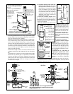
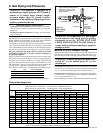
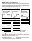
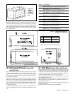
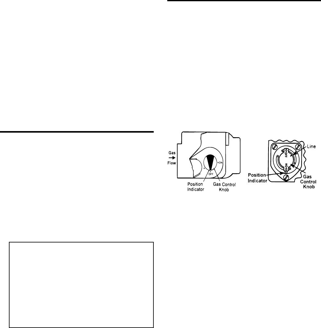
Top View of Gas Valve used on
CAUA 150 and 200
Control Knob on Top of
Gas Valve used on CAUA
250 - 400
Check/Test/Start-Up
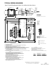
22. Check Installation & Start-Up
Check the installation prior to start-up:
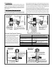
%Check clearances from combustibles. Requirements are shown in
Paragraph 4.
%If installed as a separated-combustion unit, check vent/combustion
air system to be sure that it is installed according to the instructions
in Paragraph 7A.
%Check piping for leaks and proper gas line pressure. Bleed gas lines
of trapped air. See Paragraph 9.
%Check the blower compartment to be sure that all shipping sup-
ports have been removed. Close the blower compartment door se-
curely. Heater will not operate if the blower compartment door is
not closed.
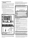
%Check electrical wiring. Be sure all wire gauges are as recommended.
A service disconnect switch should be used. Verify that fusing or
circuit breakers are adequate for the load use.
Start-Up
WARNINGS: For your safety, read before
operating. If you do not follow these instructions
exactly, a fire or explosion may result causing
property damage, personal injury, or loss of life.
• This appliance does not have a pilot. It is
equipped with an ignition device which auto-
matically lights the burner. Do not try to light
the burner by hand.
• Before operating, smell all around the appliance
area for gas. Be sure to smell next to the floor
because some gas is heavier than air and will
settle on the floor.
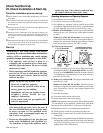
WHAT TO DO IF YOU SMELL GAS
• Do not try to light any appliance.
• Do not touch any electrical switch; do not
use any phone in your building.
• Immediately call your gas supplier from a
neighbor's phone. Follow the gas
supplier's instructions.
• If you cannot reach your gas supplier, call
your fire department.
• Use only your hand to turn the gas control ON/
OFF knob on the gas valve. Never use tools. If
the valve ON/OFF knob will not turn by hand,
do not try to repair it. Call a qualified service
technician. Force or attempted repair may re-
sult in a fire or explosion.
• Do not use this appliance if any part has been
under water. Immediately call a qualified ser-
vice technician to inspect the appliance and to
replace any part of the control system and any
gas control which has been under water.
Operating Instructions and Operating Sequence
1. Set thermostat at lowest setting.
2. Turn off all electric power to the appliance.
3. This appliance is equipped with an ignition device which
automatically lights the burner. Do not try to light the burner
by hand. Open the access door and locate the gas valve.
4. Models CAUA 150 and 200 - Locate the gas control (ON/OFF)
knob on the gas valve. Turn the gas control knob clockwise
to "OFF".
Models CAUA 250, 300, 350, and 400 - Locate the gas con-
trol (ON/OFF) knob on the gas valve. Turn knob clockwise to
align the line on the knob with the position indicator. Depress
knob and continue rotation to the "OFF" position.
5. Wait five (5) minutes to clear out any gas. Then smell for gas,
including near the floor. If you smell gas, STOP! and follow
the steps in the WARNINGS printed in the right column or
on the Operating Label on the heater. If you do not smell gas,
proceed to the next step.
6. Models CAUA 150 and 200 - Turn the gas control knob coun-
terclockwise to "ON".
Models CAUA 250, 300, 350, and 400 - Turn knob counter-
clockwise to align the line on the knob with the position indi-
cator. Allow knob to "pop up", and continue rotation to the
"ON" position.
7. Close the access door.
8. Turn on the electric power to the heater.
9. Set the thermostat to the desired setting.
NOTE: If the appliance does not operate, follow the instructions
"To Turn Off Gas to the Appliance" printed below (and on the
Operating Label on the heater). Call your service technician.
10. Thermostat calls for heat, energizing the venter motor.
11. Venter pressure switch closes, allowing the unit to fire.
12. Burner flame is sensed and in 30 seconds, the blower motor
is energized.
13. If the flame is extinguished during the main burner operation,
the integrated control system closes the main valve and must
be reset by interrupting power to the control circuit. (See
lighting instructions on the heater.).