


Form 405, Page 16
Adjusting Blower Speed
The blower speed may be adjusted to achieve the desired outlet tem-
perature, as long as the adjustment is within the temperature rise and
the static pressure limits shown on the heater rating plate. Direct drive
motors are factory set at medium speed for heating and high speed for
cooling (if ordered). Belt drive motors are factory set between maxi-
mum and minimum blower speeds.
If the duct resistance is low, the blower may deliver too high an air
volume. If the resistance is very low, the blower may deliver excess air
to overload the motor, causing the overload protector to activate. Re-
ducing the blower speed will correct these conditions. If ductwork is
added to an installation, it may be necessary to increase the blower
speed.
Direct drive motors have multi-speed taps for speed adjustment. If
your installation requires an adjustment of the blower speed, the motor
may be re-wired to an alternate tap by following these instructions.
1. Turn off the gas and electric power.
2. Remove the blower door panel.
3. Consult the wiring diagram on the heater and follow the chart below
to choose the wiring for the desired adjustment. Units are wired at
high speed for cooling (if ordered) and medium speed for heating.
Model Sizes Speed Use these two motor wires:
150, 200, 250, 350 High White and Black
Medium White and Blue
Low White and Red
300 and 400 High White and Black
Medium White and Blue
4. Cut the crimped cap for the end of the wire that you intend to use
and strip the insulation.
5. Disconnect the factory-wired connection and re-wire, using the newly
stripped wire.
6. Put a wire nut on the end of the blower motor wire that was discon-
nected.
7. Replace the heater door panel. Turn on the gas and electric. Check
for proper operation.
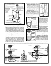
Belt drives have an adjustable pulley which permits adjustment of the
blower speed. Follow these instructions to adjust blower speed.
1. Turn off the gas and the electric power.
2. Loosen belt tension and remove the belt.
3. Loosen the set screw on the side of the pulley away from the motor.
4. To increase the blower speed, turn the adjustable half of the pul-
ley inward. To decrease the blower speed, turn the adjustable half
of the pulley outward. One turn of the pulley will change the speed
8-10%.
5. Tighten the set screw on the flat portion of the pulley shaft.
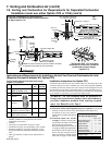
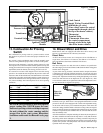
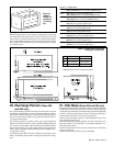
6. Replace the belt and adjust the belt tension. Adjust tension by
turning the adjusting screw on the motor base until the belt can be
depressed 3/4". (See Figure 16.) Re-tighten the lock nut on the
adjusting screw. Be sure that the belts are aligned in the pulley
grooves properly and are not angled from pulley to pulley.
7. Turn on the gas and electric. Light the heater following the instruc-
tions on the lighting instruction plate.
8. Check the motor amps with an amp meter. The maximum motor
amp rating on the motor nameplate must not be exceeded.
When service is complete, check for proper operation.
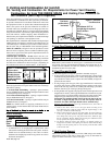
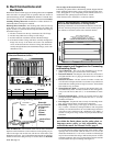
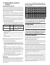
Motor Amps
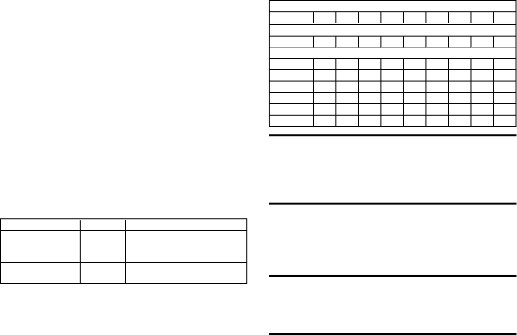
Use an amp meter to check motor amps. The chart lists full load amps
for various HP's and voltages. Amps may be adjusted downward by
reducing blower RPM or increasing duct system static pressure.
The chart below can be used for sizing line wiring but should not be
interpreted as the exact motor amps. See the motor rating plate for exact
Full Load Amps - Blower Motors (Open)
HP 1/4 1/3 1/2 3/4 1 1-1/2 2 3 5
Direct-Drive Motors
230V 1PH -- -- -- --
6.3
-- -- -- --
208V 1 PH
2.1 3.2 5.1 6.3 7.5 8.3 10.0 -- --
230V 1PH
2.3 2.8 4.4 5.5 6.5 7.5 10.2 -- --
208V 3 PH
1.1 1.4 3.0 2.9 3.7 5.6 7.0 9.0 13.4
230V 3PH
1.4 1.6 2.5 2.6 3.2 5.0 6.6 8.6 13.2
460V 3PH
0.75 0.8 1.0 1.3 1.6 2.7 3.5 4.3 6.6
575V 3PH
-- -- -- -- 1.1 1.6 2.1 3.6 5.4
Optional Belt Drive Motors
motor specifications. At final adjustment, amperes should not ex-
ceed motor nameplate amp rating. The installation must be ad-
justed to obtain a temperature rise within the range specified on
the heater rating plate.
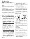
CAUTION: An external duct system static
pressure not within the limits shown on the rating
plate, or improper motor pulley or belt adjustment,
may overload the motor or cause the limit control
to activate. See Hazard Levels, page 2.
15. Gas Valve
The main operating gas valve is powered by the 24-volt control circuit
through the thermostat and safety controls. The main control valve is
of the diaphragm type providing regulated gas flow preset at the fac-
tory.
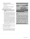
WARNING: The operating valve is the prime
safety shutoff. All gas supply lines must be free of
dirt or scale before connecting the unit to ensure
positive closure. See Hazard Levels, page 2.
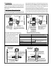
16. Ignition System
This heater is equipped with a direct spark integrated control system.
The system monitors the safety devices and controls the operation of
the blower and venter motors and the gas valve.
Ignition System Operating Sequence
On a call for heat from the thermostat, the system energizes the venter
motor and goes through a 10-second prepurge. The system verifies that
the pressure switch has changed states closing the normally open con-
tactor and that the high limit is in the closed state.
The gas valve is then energized, and the ignition system provides the
high voltage spark to the electrode to ignite the main burner gas. Burner
flame is electronically sensed by the control (minimum 1.0 microamps)
upon carryover of all burners. (A separate solid metal probe is used as
the flame sensing function. A low voltage electrical signal is imposed on
the metal probe which is electrically isolated from ground. When the
flame impinges on the flame sensing probe, the flame acts as a conduc-
tion path to ground. The flame rectifies and completes the DC circuit,
and the ignition system acknowledges the flame.)
The blower motor is energized by the system after 30 seconds of flame
sensing.
After the thermostat has been satisfied, the system de-energizes the gas
valve, the venter motor goes through a 45-second post-purge, and the
blower motor remains energized for an additional 135 seconds.
NOTE: This is a three trial system. The unit will lockout for one hour
before initiating another trial for ignition. If the unit fails after one
recycle interval, the unit will go into hard lockout and must be reset by
interrupting power or resetting the thermostat. To initiate another trial
for ignition before the one hour interval, either reset the thermostat or
interrupt power to the unit for 30 seconds.
14. Blower Motor and Drive
(cont'd)