


Optional Hardware and Software Model GFC7001E Carbon Dioxide Analyzer
Teledyne Analytical Instruments 75
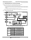
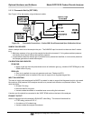
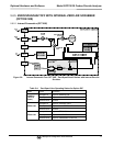
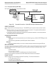
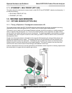
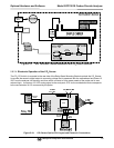
5.7.4. ETHERNET + MULTIDROP (OPT 63C)
This option allows the instrument to communicate on both RS-232 and ETHERNET networks simultaneously. It
includes the following:
RS-232 MULTIDROP (OPT 62)
ETHERNET (OPT 63A)
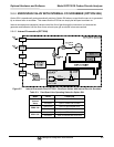
5.8. SECOND GAS SENSORS
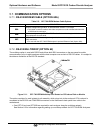
5.8.1. OXYGEN SENSOR (OPTION 65A)
5.8.1.1. Theory of Operation - Paramagnetic measurement of O
2
The oxygen sensor used in the GFC 7001E/EM Analyzer utilizes the fact that oxygen is attracted into strong
magnetic field while most other gases are not, to obtain fast, accurate oxygen measurements.
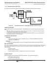
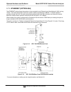
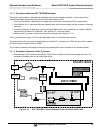
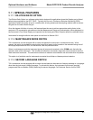
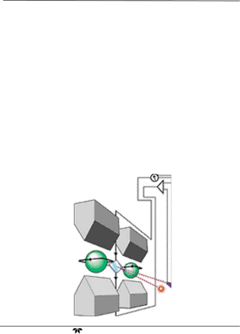
The sensor’s core is made up of two nitrogen filled glass spheres, which are mounted on a rotating suspension
within a magnetic field (see Figure 5-14). A mirror is mounted centrally on the suspension and light is shone
onto the mirror that reflects the light onto a pair of photocells. The signal generated by the photocells is passed
to a feedback loop, which outputs a current to a wire winding (in effect, a small DC electric motor) mounted on
the suspended mirror.
Oxygen from the sample stream is attracted into the magnetic field displacing the nitrogen filled spheres and
causing the suspended mirror to rotate. This changes the amount of light reflected onto the photocells and
therefore the output levels of the photocells. The feedback loop increases the amount of current fed into the
winding in order to move the mirror back into its original position. The more O
2
present, the more the mirror
moves and the more current is fed into the winding by the feedback control loop.
A sensor measures the amount of current generated by the feedback control loop which is directly proportional to
the concentration of oxygen within the sample gas mixture.
Figure 5-14: Oxygen Sensor - Principle of Operation