EPA Calibration Protocol Model GFC7001E Carbon Dioxide Analyzer
Teledyne Analytical Instruments 225
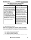
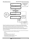
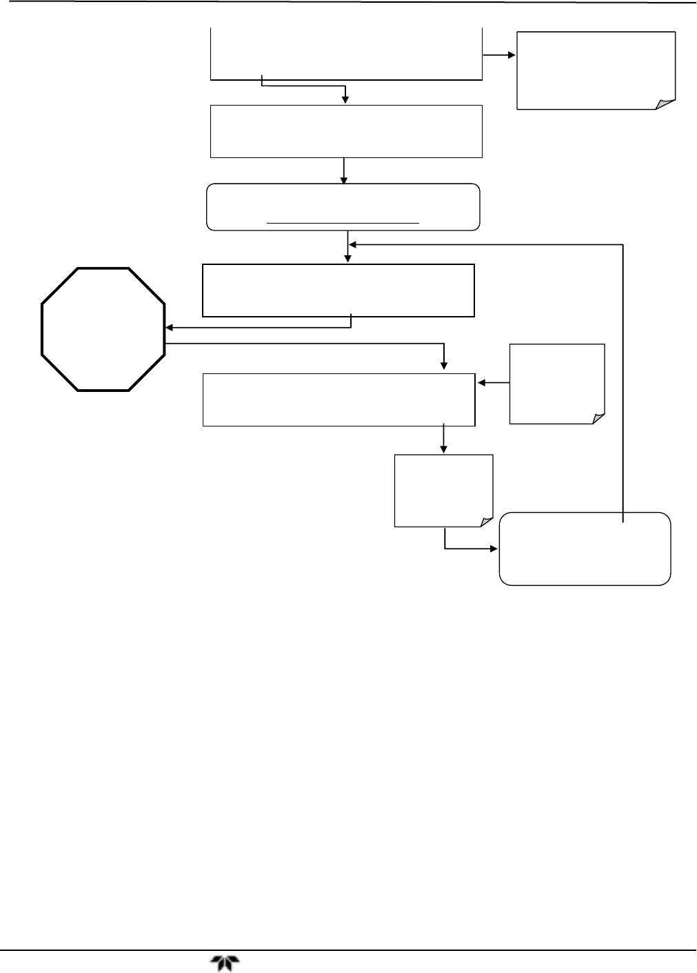
SPAN CAL M A1:CONC1=50 PPM CO = XXXX
< TST TST > ZERO SPAN CONC EXIT
Wait until
STABIL falls
below 0.2 PPM
(for M300E).
This may take
several minutes.
SAMPLE COSTB=XXXX PPB CO=XXXX
< TST TST > CAL CALZ CALS SETUP
Record the CO
reading as
displayed on the
instrument’s front
panel.
Press EXIT to
Return to the
Main SAMPLE
Display.
ACTION:
Allow Calibration Gas diluted to
proper concentration for
Midpoint N+1 to enter the sample
port.
A
CTION:
Allow calibration gas diluted to proper concentration for
Midpoint N to enter the sample port
SAMPLE A1:CONC1=50 PPM CO = XXXX
< TST TST > CAL SETUP
SAMPLE CO STB=XXXX PPB CO=XXX
X
< TST TST > CAL SETUP
Set the Display to show the
COSTB test function.
This function calculates the
stability of the CO
measurement.
Plot the analyzer responses versus the corresponding calculated concentrations to obtain a calibration
relationship. Determine the best-fit straight line (y = mx + b) determined by the method of least squares.
After the best-fit line has been drawn, determine whether the analyzer response is linear. To be considered
linear, no calibration point should differ from the best-fit line by more than 2% of full scale.
If carried out carefully, the checks described in this section will provide reasonable confidence that the GFC
7001E is operating properly. Checks should be carried out at least every 3 months as the possibility of
malfunction is always present.
If the linearity error is excessive and cannot be attributed to outside causes, check the GFC 7001E system for:
Sample pressure higher than ambient – pressurized sample gas
Leaks
Correct flow
Miscalibrated span gas tanks or bad zero gas
Miscalibrated sample pressure transducer
Failed IR detector, GFC Wheel or Sync/Demod Board
Contaminated optical bench or sample lines


