


Getting Started Model GFC7001E Carbon Dioxide Analyzer
Teledyne Analytical Instruments 46
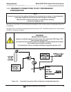
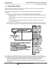
3.4.2.3. Input Gas Venting
The span gas, zero air supply and sample gas line MUST be vented in order to ensure that the gases input do
not exceed the maximum inlet pressure of the analyzer as well as to prevent back diffusion and pressure effects.
These vents should be:
At least 0.2m long;
No more than 2m long and;
Vented outside the shelter or immediate area surrounding the instrument.
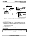
3.4.2.4. Exhaust Outlet
Attach an exhaust line to the analyzer’s EXHAUST outlet fitting. The exhaust line should be:
PTEF tubing; minimum O.D ¼”;
A maximum of 10 meters long;
Vented outside the GFC 7001E/EM Analyzer’s enclosure.
NOTE
Once the appropriate pneumatic connections have been made, check all pneumatic fittings for leaks
using the procedures defined in Section 12.3.3.
NOTE
For information on attaching gas lines to GFC 7001E/EM Analyzers with various calibration valve
options,
see Section 5.6.
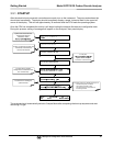
3.5. INITIAL OPERATION
NOTE
The analyzer’s cover must be installed to ensure that the temperatures of the GFC Wheel and absorption
cell assemblies are properly controlled.
If you are unfamiliar with the GFC 7001E/EM theory of operation, we recommend that you read Section Error!
Reference source not found.. For information on navigating the analyzer’s software menus, see the menu
trees described in Appendix A.1.