


Getting Started Model GFC7001E Carbon Dioxide Analyzer
Teledyne Analytical Instruments 40
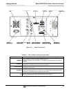
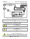
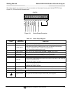
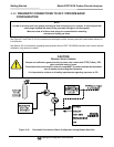
The status outputs are accessed via a 12-pin connector on the analyzer’s rear panel labeled STATUS (see
Figure 3-2). Pin-outs for this connector are:
STATUS
1 2 3 4 5 6 7 8 D
+
SYSTEM OK
HIGH RANGE
CONC VALID
ZERO CAL
SPAN CAL
DIAG MODE
Optional O
2
CAL
Figure 3-8: Status Output Connector
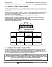
Table 3-5: Status Output Signals
REAR PANEL
LABEL
STATUS
DEFINITION
CONDITION
1 SYSTEM OK ON if no faults are present.
2 CONC VALID
OFF any time the HOLD OFF feature is active, such as during calibration or when
other faults exist possibly invalidating the current concentration measurement
(example: sample flow rate is outside of acceptable limits).
ON if concentration measurement is valid.
3 HIGH RANGE
ON if unit is in high range of either the DUAL or AUTO range modes.
4 ZERO CAL
ON whenever the instrument’s ZERO point is being calibrated.
5 SPAN CAL
ON whenever the instrument’s SPAN point is being calibrated.
6 DIAG MODE
ON whenever the instrument is in DIAGNOSTIC mode.
7 CO
2
CAL
If this analyzer is equipped with an optional CO
2
sensor, this Output is ON when that
sensor is in calibration mode.
Otherwise this output is unused.
8 O
2
CAL
If this analyzer is equipped with an optional O
2
sensor, this Output is ON when that
sensor is in calibration mode.
Otherwise this output is unused.
D EMITTER BUS The emitters of the transistors on pins 1-8 are bussed together.
SPARE
+ DC POWER + 5 VDC, 300 mA source (combined rating with Control Output, if used).
Digital Ground The ground level from the analyzer’s internal DC power supplies.