


Introduction Model GFC7001E Carbon Dioxide Analyzer
Teledyne Analytical Instruments 26
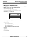
PART II – OPERATING INSTRUCTIONS
BASIC OPERATION OF THE GFC 7001E/EM ANALYZER
Step-by-Step instructions for using the display/keyboard to set up and operate the GFC 7001E/EM
Analyzer.
ADVANCED FEATURES OF THE GFC 7001E/EM ANALYZER
Step-by-Step instructions for using the GFC 7001E/EM Analyzer’s more advanced features such as the
iDAS system, the DIAG and VARS menus and the and the TEST channel analog output.
REMOTE OPERATION OF THE GFC 7001E/EM Analyzer
Information and instructions for interacting with the GFC 7001E/EM Analyzer via its several remote
interface options (e.g. via RS-232, Ethernet, its built in digital control inputs/outputs, etc.)
GFC 7001E/EM VALIDATION AND VERIFICATION
Methods and procedures for verifying the correct operation of your GFC 7001E/EM Analyzer as well as
step by step instructions for calibrating it.
EPA PROTOCOL CALIBRATION
Specific information regarding calibration requirements for analyzers used in EPA monitoring.
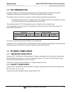
PART III – TECHNICAL INFORMATION
THEORY OF OPERATION
An in-depth look at the various principals by which the analyzer operates as well as a description of how
the various electronic, mechanical and pneumatic components of the analyzer work and interact with
each other. A close reading of this section is invaluable for understanding the analyzer’s operation.
MAINTENANCE SCHEDULE AND PROCEDURES
Description of preventative maintenance procedures that should be regularly performed on the analyzer
to assure good operating condition.
GENERAL TROUBLESHOOTING & REPAIR OF THE GFC 7001E/EM ANALYZER
This section includes pointers and instructions for diagnosing problems with the analyzer in general and
the Terminus as well as instructions on performing repairs of on the Terminus.
A PRIMER ON ELECTRO-STATIC DISCHARGE
This section describes how static electricity occurs; why it is a significant concern and; how to avoid it and
avoid allowing ESD to affect the reliable and accurate operation of your analyzer.
APPENDICES
For easier access and better updating, some information has been separated out of the manual and placed in a
series of appendices at the end of this manual. These include version-specific software menu trees, warning
messages, definitions Modbus registers and serial I/O variables as well as spare part listings, repair
questionnaires, interconnect drawing, detailed pneumatic and electronic schematics.
NOTE
The flowcharts in this manual contain typical representations of the analyzer’s display during the various
operations being described. These representations are not intended to be exact and may differ slightly
from the actual display of the instrument.