


Theory of Operation Model GFC7001E Carbon Dioxide Analyzer
Teledyne Analytical Instruments 236
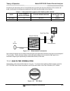
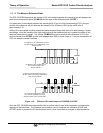
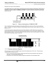
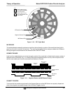
The actual flow rate of gas through the orifice (volume of gas per unit of time), depends on the size and shape of
the aperture in the orifice. The larger the hole, the more the gas molecules move at the speed of sound and
pass through the orifice. Because the flow rate of gas through the orifice is only related to the minimum 2:1
pressure differential and not absolute pressure, the flow rate of the gas is also unaffected by degradations in
pump efficiency due to age.
The critical flow orifice used in the GFC 7001E/EM is designed to provide a flow rate of 800 cc/min.
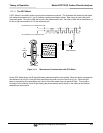
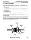
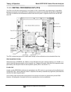
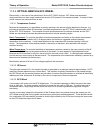
11.4.2. PARTICULATE FILTER
The GFC 7001E/EM Analyzer comes equipped with a 47 mm diameter, Teflon, particulate filter with a 5 micron
pore size. The filter is accessible through the front panel, which folds down to allow access, and should be
changed according to the suggested maintenance schedule described in Table 12-1.
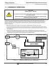
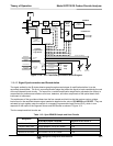
11.4.3. PNEUMATIC SENSORS
11.4.3.1. Sample Pressure Sensor
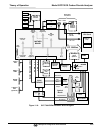
An absolute value pressure transducer plumbed to the outlet of the sample chamber is used to measure sample
pressure. The output of the sensor is used to compensate the concentration measurement for changes in air
pressure. This sensor is mounted to a printed circuit board with the Sample Flow Sensor on the sample
chamber (see Section 11.4.3.2 and Figure 3-4
11.4.3.2. Sample Flow Sensor
A thermal-mass flow sensor is used to measure the sample flow through the analyzer. The sensor is calibrated
at the factory with ambient air or N
2
, but can be calibrated to operate with samples consisting of other gases
such as CO. This sensor is mounted to a printed circuit board with the Sample Pressure Sensor on the sample
chamber (see Section 11.4.3.1 and Figure 3-4).).