


27
R-2397
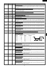
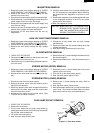
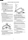
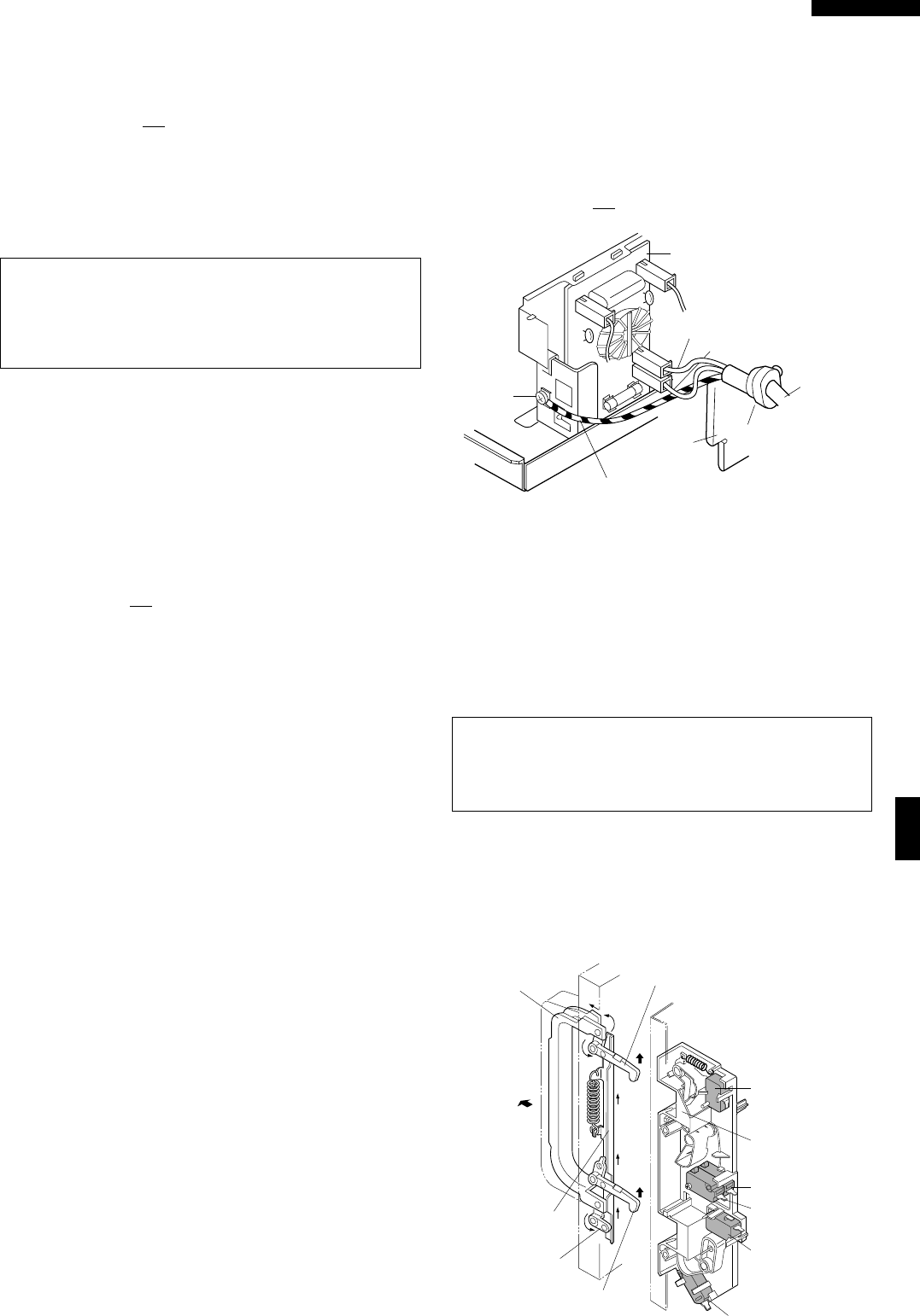
POWER SUPPLY CORD REPLACEMENT
1. CARRY OUT 3D CHECKS
2. Release the cord bushing from the rear cabinet.
3. Disconnect the brown and blue wires of the power
supply cord from the noise filter.
4. Loosen the single (1) screw holding the earth angle
and earth wire of power supply cord.
5. Remove the power supply cord.
CAUTION: DO NOT ALLOW THE WIRE LEADS OF
THE POWER SUPPLY CORD TO COME
NEAR THE HIGH VOLTAGE TRANS-
FORMER. BECAUSE THE HIGH VOLT-
AGE TRANSFORMER BECOMES HOT.
Re-install
1. Insert the power supply cord into the cord bushing.
2. Connect the brown and blue wires of power supply
cord into the terminals of noise filter, referring to
pictorial diagram.
3. Insert the green/yellow wire of power supply cord
into the earth angle, and tight the screw holding the
earth angle.
4. Re-install the cord bushing to the rear cabinet.
5. Re-install the rear cabinet to oven cavity and the
bottom plate with the eleven (11) screws and two (2)
washers.
6. CARRY OUT 4R CHECKS.
N
Screw
Green/Yellow
wire
Cord
bushing
Rear
cabinet
Power
supply
cord
Blue wire
Brown wire
Noise filter unit
L
WHT
BLK
Figure C-3. Power supply cord replacement
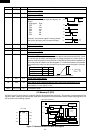
1ST LATCH, 2ND LATCH, 3RD LATCH, MONITOR, AND STOP SWITCHES REMOVAL
latch hook.
6. For 1st latch and stop switches removal
6-1. Disconnect the wire leads from the 1st latch and
stop switches.
6-2. Remove the single (1) screw and nut holding the
1st latch and stop switches to the latch hook.
CAUTION: WHEN THE 1ST LATCH SWITCH AND
2ND. LATCH SWITCH ARE INSTALLED,
THE TWO (2) TABS OF THE LATCH
HOOK SHOULD BE BROKEN.
1. CARRY OUT 3D CHECKS.
2. Remove the control panel from the oven cavity refer-
ring to “CONTROL PANEL REMOVAL”.
3. Remove the two (2) screws holding the latch hook to
the oven cavity.
4. Open the door and pull the latch hook out of the oven
cavity.
5. For 1st latch, 2nd latch or Monitor switch removal
5-1. Disconnect the wire leads from the switch.
5-2. Push the retaining tabs outward slightly and then
pull the switch forwards and remove it from the
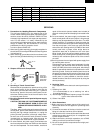
1ST, 2ND, 3RD LATCH SWITCH, STOP SWITCH AND MONITOR SWITCH ADJUSTMENT
In case 1st latch switch, 2nd latch, stop switch, 3rd latch
switch and monitor switch do not operate properly due to a
mis-adjustment, the following adjustment should be made.
1. Loosen the two (2) screws holding the latch hook.
2. With the door closed, adjust the latch hook by moving it
back and forward, or up and down. In and out play of the
door allowed by the latch hook should be less than
0.5mm. The vertical position of the latch hook should be
placed where the stop switch and 1st, 2nd, 3rd latch
switches have activated with the door closed.
The horizontal position of the latch hook should be
placed where the monitor switch has activated with the
door closed.
3. Secure the screws with washers firmly.
4. Make sure of the 1st, 2nd, 3rd latch switches, stop
switch, and monitor switch operation. If those switches
have not activated with the door closed, loose two (2)
screws holding latch hook and adjust the latch hook
position.
After adjustment, make sure of the following:
1. The stop switch and 1st, 2nd, 3rd latch switches interrupt
the circuit before the door open when the door release
lever is pulled, and then and monitor switch close the
circuit when the door is opened.
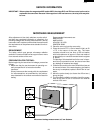
2. Re-install outer case and check for microwave leakage
around the door with an approved microwave survey
meter. (Refer to Microwave Measurement Procedure.)
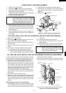
Figure C-4 Latch Switch Adjustments
Latch head
Monitor switch
Latch hook
1st. latch switch
2nd. latch switch
Stop switch
3rd. latch switch
Latch head
Joint lever
Door release
lever
Latch lever