


26
R-2397
CONTROL PANEL ASSEMBLY AND CONTROL UNIT REMOVAL
CONTROL PANEL ASSEMBLY REMOVAL
The complete control panel should be removed for re-
placement of components. To remove the control panel,
proceed as follows:
1. CARRY OUT 3D CHECKS.
2. Remove the air intake filter assembly from the base
plate.
3. Remove two (2) screws holding the control panel to
the base plate.
4. Pull down the control panel and remove it forward.
5. Disconnect two connectors (A), (B), (D), (H) and TAB
terminal (TAB1,2,3,4) from the control unit.
6. Now the control panel assembly is free.
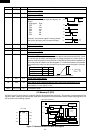
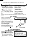
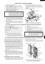
CAUTION FOR TOUCH CONTROL PANEL REMOVAL
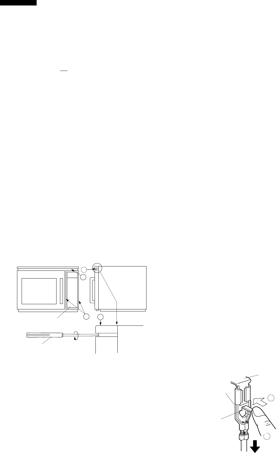
1) Hold the lower end (Position A, Fig. 1) of the touch
control panel assembly firmly while sliding it down and
toward you.
DO NOT FORCE THE CONTROL UNIT TO SLIDE
DOWN DURING REMOVAL. THIS MAY CAUSE DAM-
AGE TO THE CONTROL UNIT BY HITTING A RELAY
(RY-4) OR THE TAB TERMINALS LOCATED AT THE
FRONT OF THE OVEN CAVITY.
2) If the Touch Control Panel is hard to remove;
(1) Insert a flat head screw driver into space B . (Fig. 1)
(2) Rotate the screwdriver clockwise while holding posi-
tion C of the Touch Control Panel. (Fig. 2)
TO AVOID DAMAGE TO TOUCH CONTROL PANEL,
COVER THE TIP OF SCREWDRIVER WITH TAPE.
(3) Re-solder the Relay (RY-4) prior to reinstalling the
Touch Control Panel.
B
A
C
B
Fig. 1
Fig. 2
TOUCH CONTROL PANEL
SCREW DRIVER
Replacement of individual component is as follows:
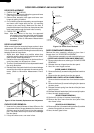
CONTROL UNIT AND CONTROL PANEL FRAME
(WITH KEY)
7. Remove two (2) screws holding the control panel
mounting angle to the panel frame.
8. Lift up the control panel mounting angle from the panel
frame.
9. Disconnect connector (G) from the control unit by
pushing the hooks of cable holder inwardly.
10.Remove four (4) screws holding the control unit to the
panel frame assembly.
11.Push down the right side two (2) hooks fixing the
control unit to the panel frame assembly, and lift up the
control unit upward.
12.Now, the control unit and control panel frame (with
key) are free.
CAUTION:
At installing control panel unit assembly to main
body set:
1. Ensure the installation of wiring-related parts with-
out negligence.
2. When inserting key cable to main body set, ensure
them free from caught-in trouble. In addition, when
installing the control panel assembly to base plate
with screws, be sure of pushing the control panel
unit upward to fix with screws firmly.
3. Do not allow any wire leads to come near the
varistor works, because it will explode and the
wire leads near by the varistor will be damaged.
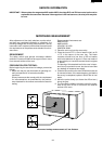
NOTE: 1. Before attaching a new key unit, remove
remaining adhesive on the control panel frame
surfaces completely with alcohol.
2. When attaching the key unit to the control
panel frame, adjust the upper edge and right
edge of the key unit to the correct position of
control panel frame.
3. Stick the key unit firmly to the control panel
frame by rubbing with soft cloth not to scratch.
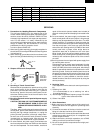
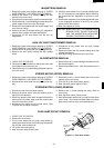
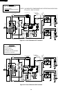
HOW TO RELEASE THE POSITIVE LOCK
®
CONNECTOR.
Procedure
1. Pushing the lever of positive lock
®
connector.
2. Pull down the connector from the terminal.
3. Now, the connector is free.
Note: If the positive lock
®
has a insulation sleeve, first
remove it. If you do not so, you can not push the
lever of positive lock
®
.
CAUTION: The positive lock
®
terminal can not be dis-
connected by only pulling. Because once
you (Service personnel) have connected the
positive lock
®
connector to the terminal, the
positive lock
®
connector has been locked.
Figure C-2. How to release the positive lock connector.
Terminal
Push
Pull down
1
2
Lever
Positive lock®
connector