


R-2397
18
DESCRIPTION OF LSI
LSI(IZA646DR)
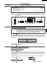
The I/O signal of the LSI(IZA646DR) is detailed in the following table.
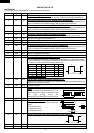
Pin No. Signal I/O Description
1 VREF IN Reference voltage input terminal.
A reference voltage applied to the A/D converter in the LSI. Connected to GND.(0V)
2 IN7 IN
Temperature measurement input: MAGNETRON THERMISTOR.
By inputting DC voltage corresponding to the temperature detected by the thermistor, this
input is converted into temperature by the A/D converter built into the LSI.
3 IN6 IN
Temperature measurement input: EXHAUST THERMISTOR.
By inputting DC voltage corresponding to the temperature detected by the thermistor, this
input is converted into temperature by the A/D converter built into the LSI.
4 IN5 IN A/D input for troubleshooting Magnetron 1.
5 IN4 IN
Terminal to change functions according to the model.
Signal in accordance with the model in operation is applied to set up its function.
6 IN3 IN A/D input for troubleshooting Magnetron 2.
7 IN2 IN Connected to GND.(0V)
8 IN1 IN Terminal not used.
9 IN0 IN
Temperature measurement input: INTAKE THERMISTOR.
By inputting DC voltage corresponding to the temperature detected by the thermistor, this
input is converted into temperature by the A/D converter built into the LSI.
10 P47 OUT Terminal not used.
11 P46 OUT Memory (EEPROM) clock output.
12 P45 IN/OUT Memory (EEPROM) data input/output.
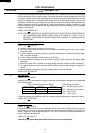
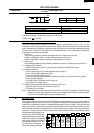
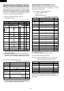
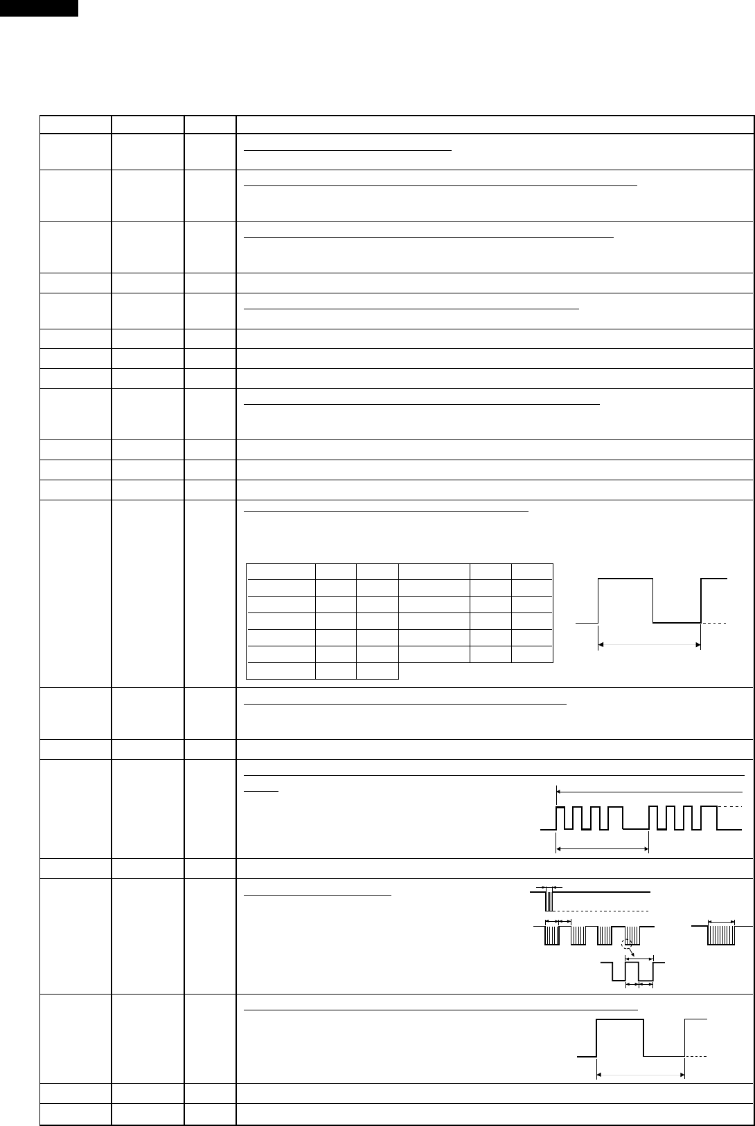
13-14 P44-P43 OUT Magnetron high-voltage circuit driving signal.
To turn on and off the cook relay. In 100% power level operation, "L" level during cooking;
"H" level otherwise. In other power level operation (90,80,70,60,50,40,30,20,10 or 0%),
"H" and "L" level is repeated according to power level.
Power level ON OFF Power level ON OFF
100% 48sec. 0sec. 40% 22sec. 26sec.
90% 44sec. 4sec. 30% 16sec. 32sec.
80% 40sec. 8sec. 20% 12sec. 36sec.
70% 36sec. 12sec. 10% 8sec. 40sec.
60% 32sec. 16sec. 0% 0sec. 48sec.
50% 26sec. 22sec.
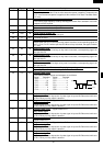
15 P42 OUT Power supply output at thermistor detecting circuit.
(Output -5V in cooking only, but apply high impedance to others to prevent thermistor from
electrolytic corrosion ocurrence.)
16 P41 OUT Terminal not used.
17 P40 OUT
Oven lamp, Blower motor and Stirrer motor driving signal. (Square Waveform :
50Hz)
To turn on and off the shut-off relay (RY1). The
Square waveform voltage is delivered to the
RY1 relay driving circuit and
relays(RY3,RY4,COOK RELAY) control circuit.
18-22 P37-P33 OUT Terminal not used.
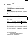
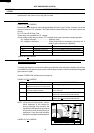
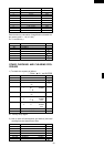
23 P32 OUT
Signal to sound buzzer.
This signal is to control the 2.5kHz continuous
signal.
A: key touch sound.
B: Guydance sound.
C: Completion sound.
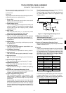
24 P31 IN Signal synchronized with commercial power source frequency.
This is basic timing for all time processing of LSI.
25 P30 OUT Terminal not used.
26 CNVSS IN Connected to Vc.(-5V)
GND
-5V
48 sec.
OFF
ON
H
L
20 msec
During cooking
A
B
C
0.12 sec
2.4 sec
1.2 sec
1.2 sec
GND
-5V
T
200µsec.
200µsec.
H : GND
L (-5V)
20 msec