


15
R-2397
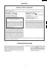
TEST PROCEDURES
PROCEDURE
LETTER
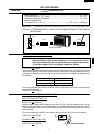
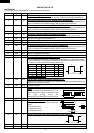
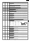
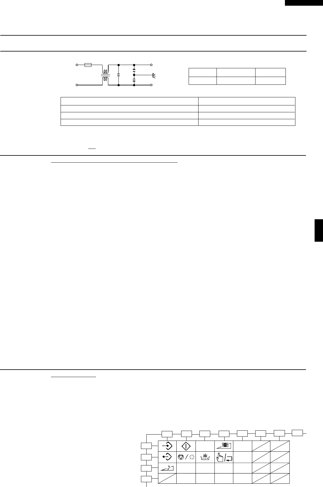
COMPONENT TEST
L (min) Cx ± 20% Cy ± 20%
0.5mH 0.22 µF 4700 pF
MEASURING POINT INDICATION OF OHMMETER
Between N and L Open circuit
Between terminal N and WHITW Short circuit
Between terminal L and BLK Short circuit
If incorrect readings are absorbed, replace the noise filter.
CARRY OUT 4R CHECKS.
L
N
L
L
F1
Cy
BLK
WHT
Cx
N TOUCH CONTROL PANEL ASSEMBLY TEST
The touch control panel consists of circuits including semiconductors such as LSI, IC, etc.
Therefore, unlike conventional microwave ovens, proper maintenance cannot be performed with
only a voltmeter and ohmmeter. In this service manual, the touch control panel assembly is divided
into two units, Control Unit and Switch Unit, troubleshooting by unit replacement is described
according to the symptoms indicated.
1. Key Unit
The following symptoms indicate a defective key unit. Replace the key unit.
a) When touching the pads, a certain pad produces no signal at all.
b) When touching the pads, sometimes a pad produces no signal.
2. Control Unit
The following symptoms may indicate a defective control unit. Replacing the control unit.
2-1 Programming problems.
a) When touching the pads, a certain group of pads do not produce a signal.
2-2 Display problems.
a) For a certain digit, all or some segments do not light up.
b) For a certain digit, brightness is low.
c) Only one indicator does not light.
d) The corresponding segments of all digits do not light up; or they continue to light up.
e) Wrong figure appears.
f) A certain group of indicators do not light up.
g) The figure of all digits flicker.
2-3 Other possible problems caused by defective control unit.
a) Buzzer does not sound or continues to sound.
b) Cooking is not possible.
Note: When defective components, (the Control Unit or Key Unit) are replaed, the defective part
or parts must be properly packed for return in the shipping carton. with its cushion material,
in which the new replacement part was shipped to you.
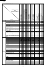
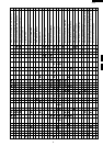
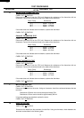
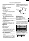
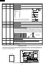
O KEY UNIT TEST
f the display fails to clear when the STOP/CLEAR pad is depressed, first verify the flat ribbon is
making good contact, verify that the door sensing switch (stop switch ) operates properly; that is the
contacts are closed when the door is closed and open when the door is open. If the door sensing
switch (stop switch ) is good, disconnect the flat ribbon cable that connects the key unit to the control
unit and make sure the door sensing switch is closed (either close the door or short the stop switch
connector ). Use the key unit matrix indicated on the control panel schematic and place a jumper
1
3
4
5
6
7
8
9
0
G 1
G 2G 3G 4
G 5
G 6
G 7
G 8
G 9
G 10
G 11
G 12
2
X2
wire between the pins that corre-
spond to the STOP/CLEAR pad
making momentary contact. If the
control unit responds by clearing
with a beep, the key unit is faulty
and must be replaced. If the con-
trol unit does not respond, it is
faulty and must be replaced.