


R-2397
17
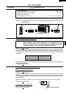
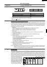
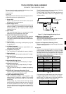
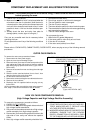
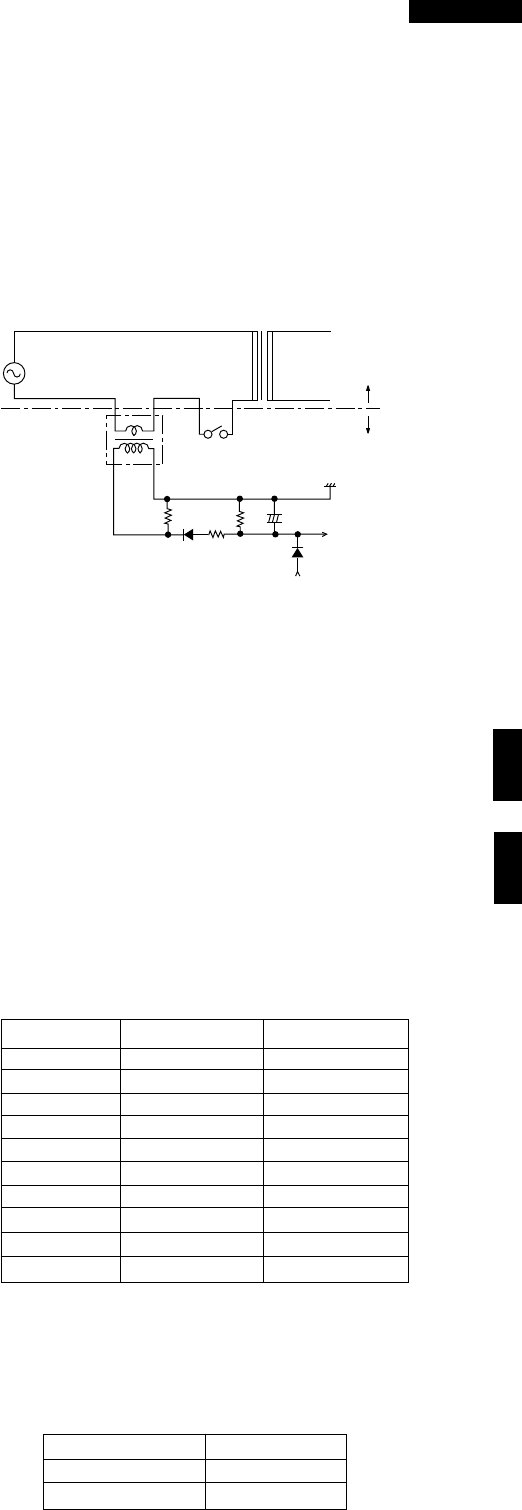
This AC voltage is then half wave rectified by D61/D62
and smoothed (filtered) by C61/C62.
This AC voltage is the input to the IN3 and IN5 ports of
IC1, which determines if there is a magnetron / high
voltage problem.
Figure T-1. High Voltage Monitoring Circuit
14) Magnetron Temperature Circuit.
(Detect Noload or Fan Lock)
This is a circuit for transmitting output change of thermistor
(Magnetron Temperature Sensor) to IC1.
15) Intake Air Temperature Detecting Circuit.
This is a circuit for transmitting output change of thermistor
(Intake Air Sensor) to IC1.
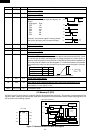
2. Key Unit
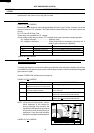
The key unit is composed of a matrix circuit in which when
a key it touched, one of signals P11, P12, P15, P16 and
P17 generated by the LSI, is passed through the key and
returned to the LSI as one of signals R0--R3. This model
has 20 Memory pads. When the oven is shipped, Memory
pad 1 to 10 are set as follows: fig.1.
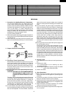
Memory No. Cook Time Output Power
1 5sec. 100%
2 10sec. 100%
3 20sec. 100%
4 30sec. 100%
5 40sec. 100%
6 50sec. 100%
7 1min. 100%
8 1min.15sec. 100%
9 1min.30sec. 100%
10 2min. 100%
(fig. 1)
This model has a double quantity pad. When the oven
is shipped, Magnification "1.8" is preset in the double
quantity pad. This model has an defrost pad. When the
oven is shipped, defrost is set as follows: fig.2.
1 STAGE
POWER 10%
OVEN ON/OFF ON
(fig. 2)
TOUCH CONTROL PANEL ASSEMBLY
OUTLINE OF TOUCH CONTROL PANEL
The touch control section consists of the following units as
shown in the touch control panel circuit.
(1) Control Unit
(2) Key Unit
The principal functions of these units and the signals commu-
nicated among them are explained below.
1. Control Unit
Signal of key touch and oven function control are all
processed by one microcomputer.
1) Power Supply Circuit
This circuit changes output voltage at the secondary side
of the low voltage (T1) transformer to volatges required
at each part by full wave rectifying circuit, constant
voltage circuit, etc..
2) ACL Circuit
This is an Auto-clear Circuit, i.e., a reset circuit, which
enables IC1 to be activated from initial state.
3) Power SYNC Signal Generating Circuit
This is a circuit for generating power SYNC signal by
virtue of the secondary side output of transformer T1.
This signal is used for a basic frequency to time process-
ing and so on.
4) Clock Circuit
This is a circuit for controlling clock frequency required
for operating IC1.
5) IC1 (Main Processor)
This is a one-chip microcomputer, responsible for con-
trolling the entire control unit.
6) IC2 (Memory Processor)
This is a memory IC, responsible for memory function.
7) Display Circuit
This is a circuit for driving display tubes by IC1 output.
8) Key Input Circuit
This is a circuit for transmitting key input information to
IC1.
9) Sound-body Driving Circuit
This is a circuit for driving sound body by IC1 output.
10) Relay Driving Circuit
This is a circuit for driving output relay by IC1 output.
11) Stop Switch Circuit
This is a circuit for driving IC1 to detect door opening/
closing.
12) Exhaust Air Temperature Detecting Circuit
This is a circuit for transmitting output change of thermistor
(Exhaust Air Temperature Sensor) to IC1.
13) High Voltage Monitoring Circuit.
This circuit detects problems in the magnetron / high
voltage circuit by sensing a variation in the current
flowing through the primary winding of the high voltage
transformer.
During heating, the primary current of the high voltage
transformers also flows through the primary winding of
the current transformers CT1 and CT2. This causes a
current to be induced in the secondary windings of CT1/
CT2 and results in an AC voltage which is determined by
R61/R62.
HIGH VOLTAGE TRANSFORMER
HIGH VOLTAGE CIRCUIT
MAIN BODY SIDE
T/C SIDE
CT1 or CT2
RY3 or RY4
R61 or
R62
R65 or
R66
D61 or
D62
R63 or
R64
Vc
C61 or C62
IC1
IN3 or
IN5 PORT
D63 or
D64