


25
R-2397
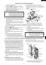
MAGNETRON REMOVAL
1. Remove the outer case cabinet referring to "OUTER
CASE REMOVAL" and CARRY OUT 3D CHECKS.
2. Remove the eleven (11) screws holding the rear
cabinet to the oven cavity.
3. Disconnect the power supply cord from the noise filter.
4. Remove the one (1) screw holding the earth wire of the
power supply cord to the noise filter angle.
5. Remove the rear cabinet with the power supply cord
from the oven cavity.
6. Remove the two (2) screws holding the magnetron
exhaust duct to upper and lower waveguide.
7. Disconnect all the wire leads from the two (2)
magnetrons.
8. Carefully remove each four (4) screws holding each
two (2) magnetrons to waveguide. When removing
the screws hold the magnetron to prevent it from
falling.
9. Remove the magnetron from the waveguide with care
so the magnetron antenna is not hit by any metal
object around the antenna.
10.Now, the magnetron is free.
CAUTION: WHEN REPLACE THE MAGNETRON,
BE SURE THE R.F. GASKET IS IN PLACE
AND THE MAGNETRON MOUNTING
SCREWS TIGHTENED SECURELY.
1. Remove the outer case cabinet referring to "OUTER
CASE REMOVAL" and CARRY OUT 3D CHECKS.
2. Disconnect the all wire leads from the magnetron(s).
3. Remove the wire holder holding the high voltage
wires.
HIGH VOLTAGE TRANSFORMER REMOVAL
4. Disconnect all wire leads from the high voltage
transformer(s).
5. Remove the each two (2) screws holding each high
voltage transformer.
6. Now, high voltage transformer(s) is (are) free.
BLOWER MOTOR REMOVAL
1. CARRY OUT 3D CHECKS.
2. Disconnect the wire leads from the blower motor and
the blower motor thermal cut-out.
3. Remove the one (1) screw holding the blower motor to
the oven cavity.
4. Remove the one (1) screw holding the blower motor to
the chassis support.
5. Remove the blower motor. Now, the blower motor is
free.
STIRRER MOTOR (UPPER) REMOVAL
1. Remove the outer case cabinet referring to "OUTER
CASE REMOVAL" and CARRY OUT 3D CHECKS.
2. Disconnect the wire leads from the stirrer motor (up-
per).
3. Remove the one (1) screw holding the stirrer motor
(upper) to the oven cavity.
4. Turn and lift up the stirrer motor (upper).
5. Now, the stirrer motor (upper) is free.
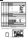
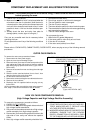
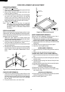
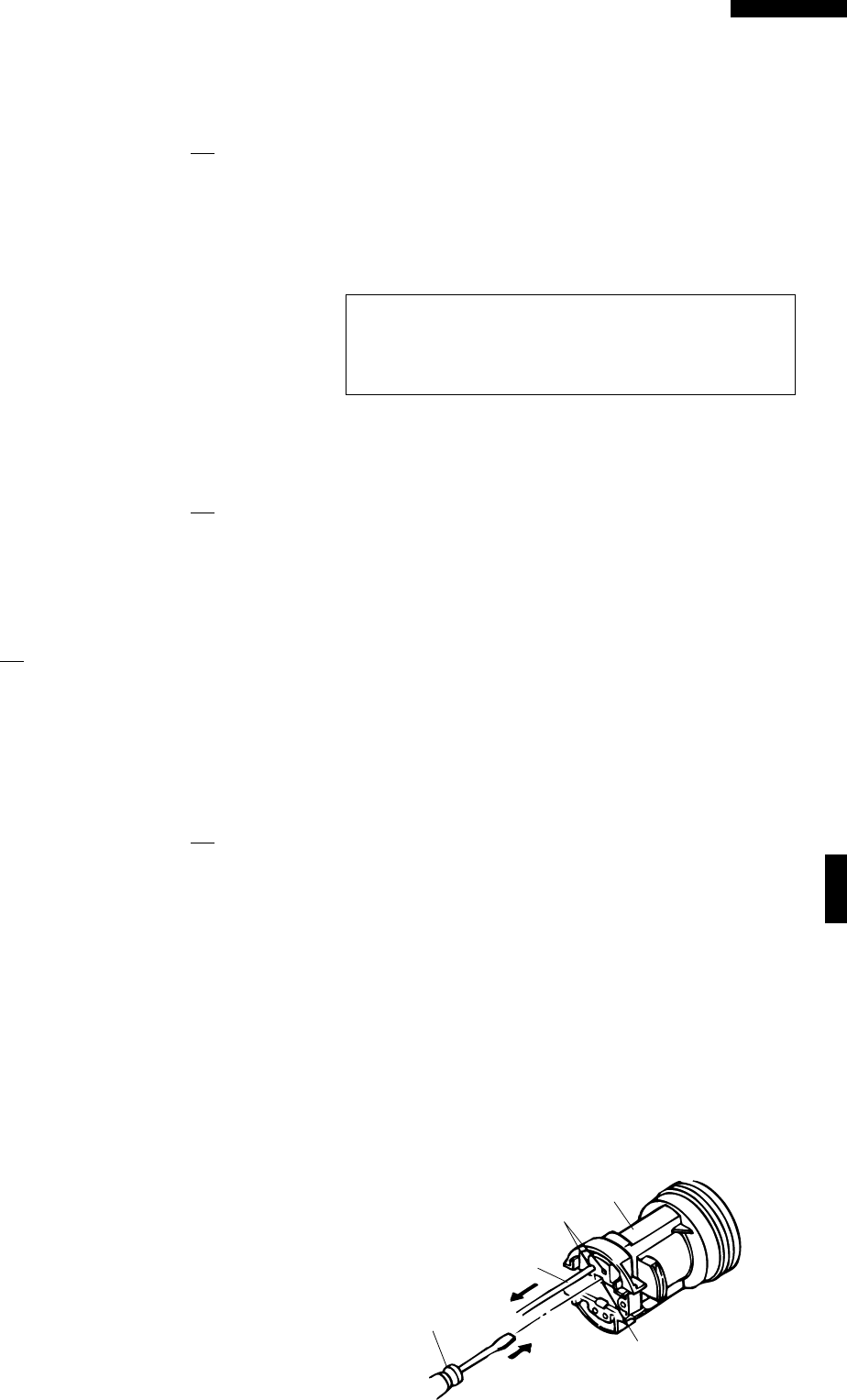
Oven lamp
socket
Terminal
Wire lead
Flat type small
screw driver
Terminal hole
OVEN LAMP SOCKET REMOVAL
1. CARRY OUT 3D CHECKS.
2. Remove the oven lamp.
3. Pull the wire leads from the oven lamp socket by
pushing the terminal hole of the oven lamp socket with
the flat type small screw driver.
4. Lift up the oven lamp socket.
5. Now, the oven lamp socket is free.
Figure C-1. Oven lamp socket
STIRRER MOTOR (LOWER) REMOVAL
1. Disconnect oven from the power supply.
2. Remove the stirrer motor cover by snipping off the
material in four portions.
3. Where the portions have been snipped off bend the
portions flat. No sharp edge must be evident after
removal of the stirrer cover.
4. Disconnect wire leads from the stirrer motor. (See
"Positive lock connector removal")
5. Remove one (1) screw holding the stirrer motor to
oven cavity.
6. Now, the stirrer motor (lower) is free.
7. After replacement use the one (1) screw to fit the stirrer
motor cover. (This screw has been fitted to the base
plate near the stirrer motor cover beforehand.)