


24
R-2397
CAUTION:DISCHARGE HIGH VOLTAGE CAPACI-
TOR BEFORE TOUCHING ANY OVEN
COMPONENTS OR WIRING.
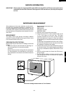
COMPONENT REPLACEMENT AND ADJUSTMENT PROCEDURE
WARNING: Avoid possible exposure to microwave energy. Please follow the instructions below
before operating the oven.
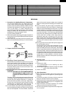
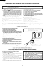
1. CARRY OUT 3D CHECKS.
2. Make sure that a definite” click” can be heard when the
microwave oven door is unlatched. (Hold the door in
a closed position, then pull the door release lever with
one hand, this causes the latch leads to rise, it is then
possible to hear a “click’ as the door switches oper-
ate.)
3. Visually check the door and cavity face plate for
damage (dents, cracks, signs of arcing etc.).
Carry out any remedial work that is necessary before
operating the oven.
Do not operate the oven if any of the following conditions
exist;
1. Door does not close firmly.
2. Door hinge, support or latch hook is damaged.
3. The door gasket or seal or damaged.
4. The door is bent or warped.
5. There are defective parts in the door interlock system.
6. There are defective parts in the microwave generating
and transmission assembly.
7. There is visible damage to the oven.
Do not operate the oven:
1. Without the RF gasket (Magnetron).
2. If the wave guide or oven cavity are not intact.
3. If the door is not closed.
4. If the outer case (cabinet) is not fitted.
Please refer to ‘OVEN PARTS, CABINET PARTS, DOOR PARTS’, when carrying out any of the following removal
procedures:
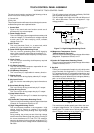
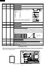
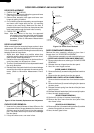
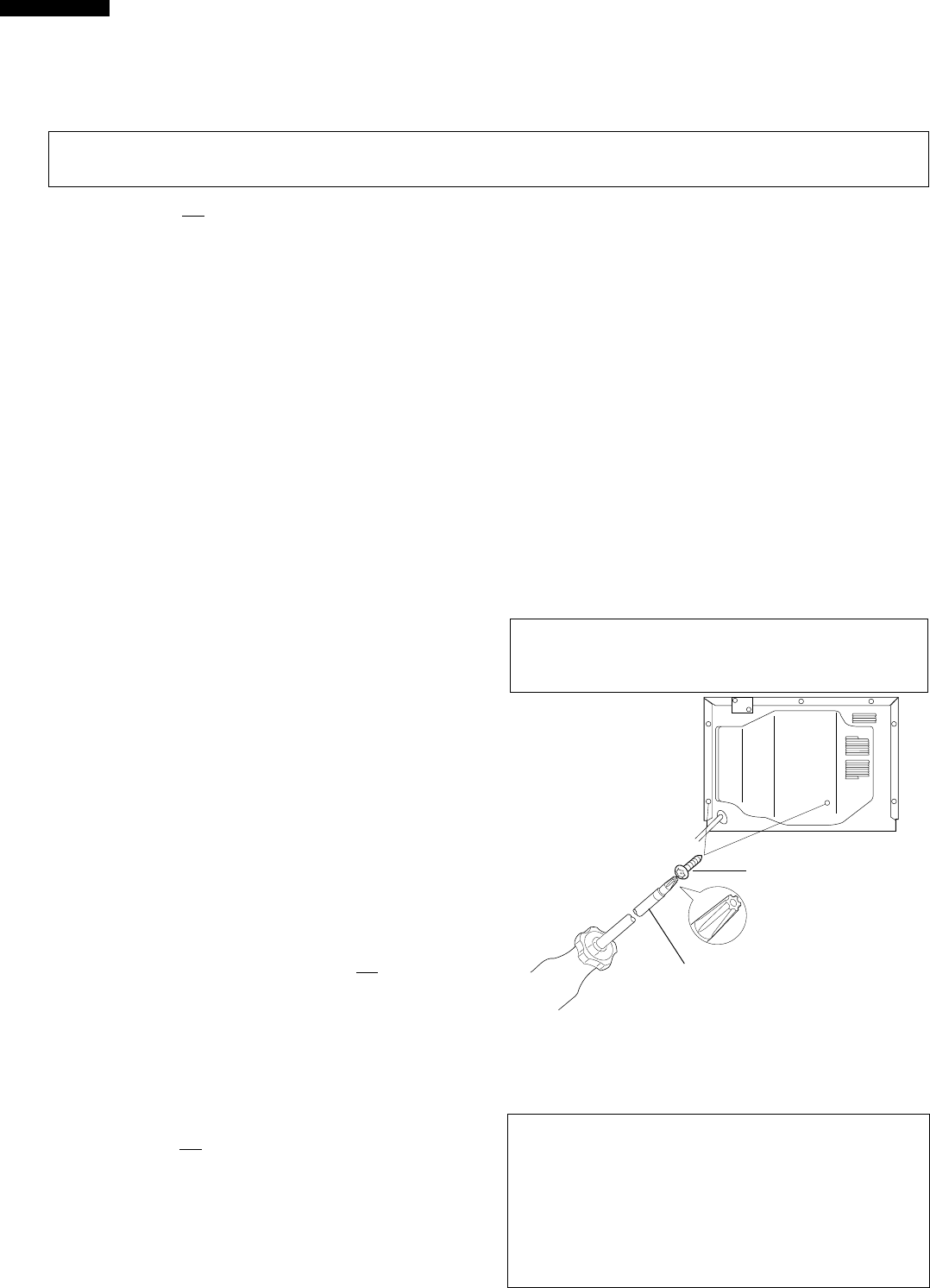
OUTER CASE REMOVAL
Special screw
CAUTION
1. DO NOT REPLACE ONLY HIGH VOLTAGE REC-
TIFIER. WHEN REPLACE IT, REPLACE HIGH
VOLTAGE RECTIFIER ASSEMBLY.
2. WHEN REPLACING HIGH VOLTAGE RECTIFIER
ASSEMBLY, ENSURE THAT THE CATHODE
(EARTH) CONNECTION IS SECURELY FIXED
TO THE CHASSIS WITH A EARTHING SCREW.
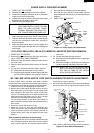
6. Now, the two (2) high voltage capacitors are free.
To remove the components, proceed as follows.
1. CARRY OUT 3D CHECKS.
2. Remove two (2) screws holding earth side terminals of
high voltage rectifier assemblies.
3. Disconnect all the leads and terminals of high voltage
rectifier assembly from high voltage capacitor.
4. Remove two (2) screws holding capacitor holder to the
right side of oven cavity and remove the capacitor
holder.
5. Now, high voltage rectifier assembly should be free.
HIGH VOLTAGE COMPONENTS REMOVAL
(High Voltage Capacitor and High Voltage Rectifier Assembly)
Screw Driver
(Type; LHSTIX DLR4-100T)
To remove the outer case, proceed as follows.
1. Disconnect oven from power supply.
2. Open the oven door and wedge it open.
3. Remove the two (2) screws from the lower portion of the
rear cabinet and lower left portion of the oven cabinet
back side using by special screw drive (Type; LHSTIX
DLR4-100T).
4. Remove the screws from rear and along the side edge
of case.
5. Slide the entire case back about 3cm to free it from
retaining clips on the cavity face plate.
6. Lift the entire case from the oven.
7. Remove the screws holding the rear cabinet to the oven.
8. Remove the rear cabinet.
9. Discharge the HV capacitor before carrying out any
further work.
10.Do not operate the oven with the outer case removed.
N.B.; Step 1,2 and 9 form the basis of the
3D checks.