


16
R-2397
TEST PROCEDURES (CONT'D)
PROCEDURE
LETTER
COMPONENT TEST
If a specific pad does not respond, the above method may be used (after clearing the control unit)
to determine if the control unit or key pad is at fault.
CARRY OUT 3D CHECKS.
Remove the outer case and check voltage between Pin Nos. 5 and 7 of the connector (A) on the
control unit with an A.C. voltmeter. The meter should indicate 230 volts, if not check control unit
circuity.
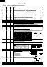
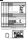
RY1, RY3 and RY4 Relay Test
These relays are operated by D.C. voltage.
Check voltage at the relay coil with a D.C. voltmeter during the microwave cooking operation.
DC. voltage indicated ............................ Defective relay.
DC. voltage not indicated ...................... Check diode which is connected to the relay coil. If
diode is good, control unit is defective.
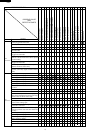
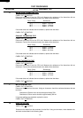
RELAY SYMBOL OPERATIONAL VOLTAGE CONNECTED COMPONENTS
RY1 APPROX. 19.0V D.C. Oven lamp, Blower motor and Stirrer motor
RY3 APPROX. 16.0V D.C. Power transformer 1
RY4 APPROX. 18.0V D.C. Power transformer 2
CARRY OUT 4R CHECKS.
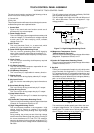
P RELAY TEST
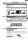
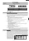
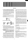
Q PROCEDURES TO BE TAKEN WHEN THE FOIL PATTERN ON THE PRINTED WIRING
BOARD (PWB) IS OPEN
To protect the electronic circuits, this model is provided with a fine foil pattern added to the primary
on the PWB, this foil pattern acts as a fuse. If the foil pattern is open, follow the troubleshooting guide
given below for repair.
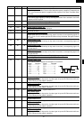
Problem: POWER ON, indicator does not light up.
CARRY OUT 3D CHECKS.
STEPS OCCURANCE CAUSE OR CORRECTION
1 The rated AC voltage is not present at Check supply voltage and oven power cord.
POWER terminal of CPU connector (CN-A).
2 The rated AC voltage is present at primary Low voltage transformer or secondary circuit defective.
side of low voltage transformer. Check and repair.
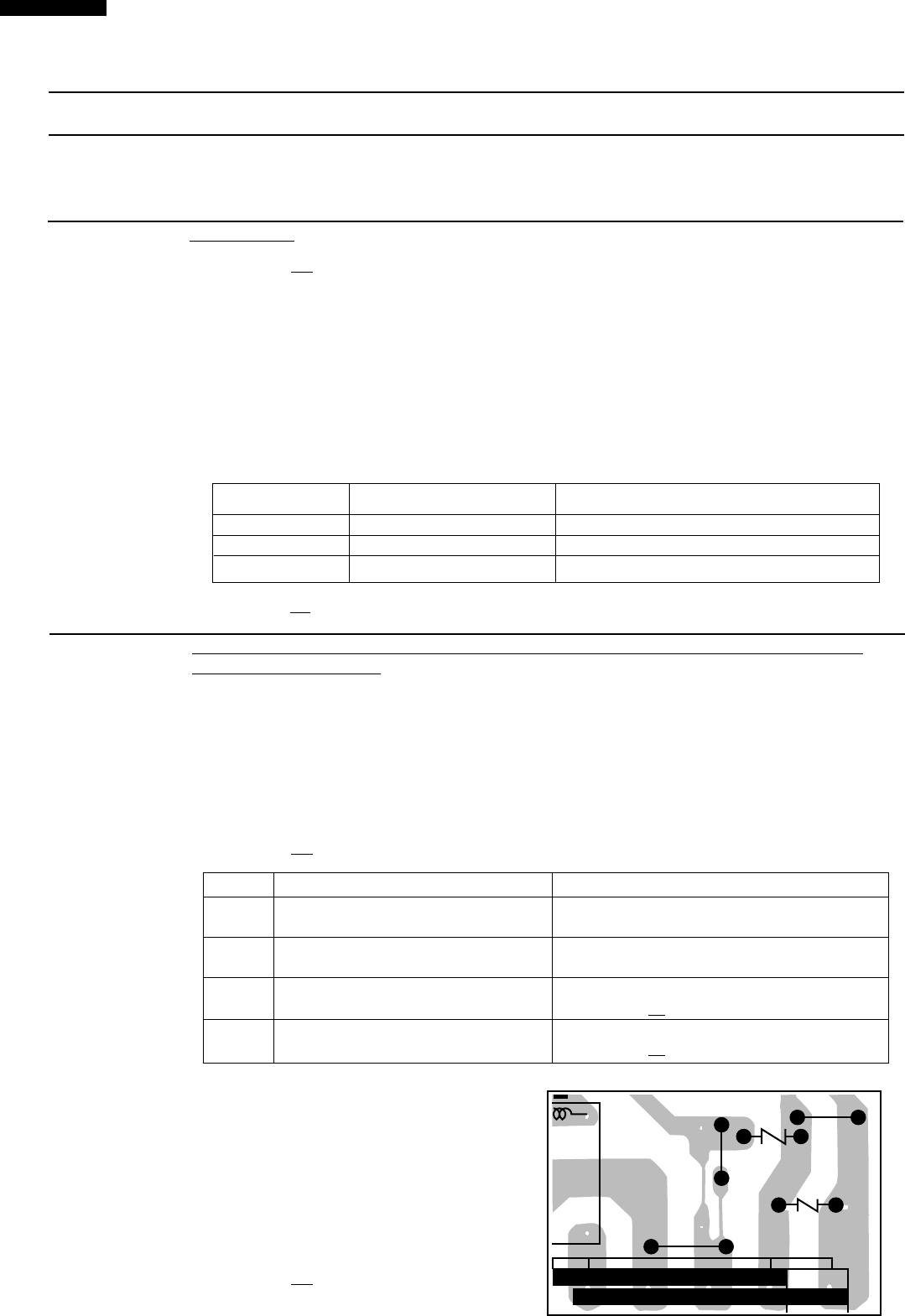
3 Only pattern at "a" is broken. *Insert jumper wire J24 and solder.
(CARRY OUT 3D CHECKS BEFORE REPAIR)
4 Pattern at "a" and "b" are broken. *Insert the coil RCILF2003YAZZ between "c" and "d".
(CARRY OUT 3D CHECKS BEFORE REPAIR)
NOTE: *At the time of these repairs, make a
visual inspection of the varistor for
burning damage and examine the
transformer with tester for the presence
of layer short-circuit (check primary coil
resistance). If any abnormal condition
is detected, replace the defective parts.
CARRY OUT 4R CHECKS.
(J29)
(VRS2)
VRS1
(J24)
(J23)
(9)9(7)5(3)3(1)
RY1
D81
c
a
b
d