


13
R-2397
TEST PROCEDURES
PROCEDURE
LETTER
COMPONENT TEST
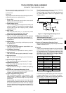
G WEAK POINT A017
CARRY OUT 3D CHECKS.
If the weak point A017 is blown, there could be a shorts or grounds in electrical parts or wire harness.
Check them and replace the defective parts or repair the wire harness.
CARRY OUT 4R CHECKS.
CAUTION: Only replace weak point A017 with the correct value replacement.
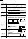
H FUSE F6.3A TEST
CARRY OUT 3D CHECKS.
If the fuse F6.3A is blown when the door is opened, check the latch switch, monitor switch and
monitor resistor.
If the fuse F6.3 is blown by incorrect door switching replace the defective switch(s) and the fuse
F6.3A.
CARRY OUT 4R CHECKS.
CAUTION: Only replace fuse with the correct value replacement.
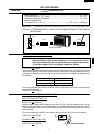
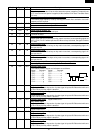
I THERMAL CUT-OUT TEST
CARRY OUT 3D CHECKS.
Disconnect the leads from the terminals of the thermal cut-out. Then using an ohmmeter, make a
continuity test across the each two terminals as described in the table below.
CARRY OUT 4R CHECKS.
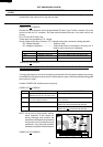
Table: Thermal Cut-out Test
Temperature of “ON” Temperature of “OFF” Indication of ohmmeter
Parts Name condition (closed circuit). condition (open circuit). (When room temperature
(˚C) (˚C) is approx. 20˚C.)
Thermal cut-out 145˚C This is not resetable type. Above 145˚C Closed circuit.
Thermal cut-out 115˚C This is not resetable type. Above 115˚C Closed circuit
If incorrect readings are obtained, replace the thermal cut-out.
An open circuit oven thermal cut-out 115˚C indicates that the oven cavity has over heated, this may
be due to no load operation.
An open circuit magnetron thermal cut-out 145˚C indicates that the magnetron has overheated, this
may be due to resistricted ventilation, cooling fan failure or a fault condition within the magnetron
or HV circuit.
An open circuit blower motor thermal cut-out 115˚C indicates the blower motor winding has
overheated, this may be due to resisted ventilation or locked cooling fan.
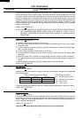
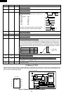
CARRY OUT 3D CHECKS.
Disconnect the leads from the monitor resistor. Using an ohmmeter and set on a low range. Check
between the terminals of the monitor resistor.
The resistance of monitor resistor should be read approx. 4.3Ω.
If incorrect readings are obtained, replace the monitor resistor.
CARRY OUT 4R CHECKS.
J MONITOR RESISTOR TEST