SMC sierra monitor corporation Sentry Instruction Manual - Version 6
INSTALLATION
Page: 19
3.5 CONTROLLER INSTALLATION
3.5.1 CONTROLLER CONFIGURATIONS
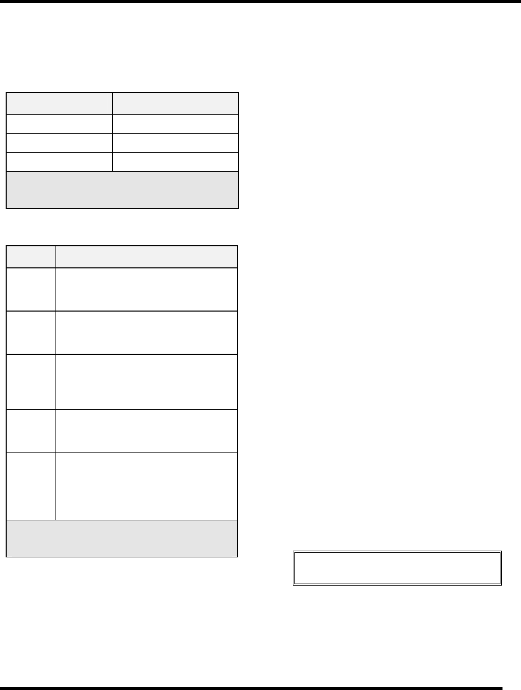
Table 3-5 lists the number of sensor modules which can be
operated on each controller model.
Model Controller Capacity
5000-02 2 Sensor Modules
5000-04 4 Sensor Modules
5000-08 8 Sensor Modules
Table 3-5
Sentry Controller Capacity
Table 3-6 lists and describes Sentry controller enclosure
options.
Model Description
5380-00 Standard configuration, controller
intended for installation in instrument
rack. Wiring to back connector panel.
5381-00 Controller supplied with bezel for panel
or chassis installation. Wiring to back
connector panel.
5382-00 Wall mount configuration includes a
mounting panel and brackets, display is
side mounted. Wiring to side facing
panel.
5383-00 NEMA-4X Enclosure with latching front
door and window for viewing display.
Wiring to front facing terminal strips.
5395-00 NEMA-7 Explosion Proof Enclosure
with screw in window for viewing of
display and external switches for
operation of keypad. Wiring to side
facing panel.
Table 3-6
Sentry Enclosure Options
3.5.2 CONTROLLER MOUNTING
3.5.2.1 RACK MOUNTED CONTROLLER
The instrument rack should be installed in a 19" electronic
cabinet at eye level. Care should be taken to avoid heat
from other instruments under the controller.
3.5.2.2 CHASSIS MOUNTED CONTROLLER
The chassis mounted controller is provided with a pre-
installed bezel and a template for the chassis cut-out. An
angle bracket is also provided to support the cantilever of
the controller. Select an appropriate location at
approximately eye level providing rear access for the
module and alarm wiring.
3.5.2.3 WALL MOUNTED CONTROLLER
The wall mounted controller is provided on a sheet metal
panel containing brackets which allow for removal of the
controller. Select a location, where module and alarm
wiring can be run up or down the wall for distribution, and
bolt the panel to the wall.
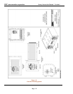
3.5.2.4 NEMA ENCLOSED CONTROLLER
Mount the NEMA enclosed controller on a vertical surface
with the display at approximately eye level. Mounting feet
are supplied with the enclosure for external mounting bolts.
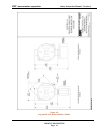
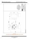
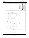
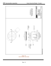
Figure 1-3. Although the enclosure is designed for
exposure to weather, normal measures to protect the
system from harsh conditions are recommended. It is
particularly important to avoid exposure of the display to
direct sunlight as this can cause fading of the display
during very hot weather.
3.5.2.5 WIRING CONNECTIONS
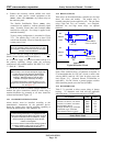
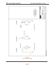
Channel wiring connections at the controller (except
NEMA-4X) and at the module are made using a quick
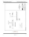
connect terminal strip. Figure 3-7. The terminal can be
operated using an actuator (supplied in the system
accessory bag) or by pressing a small screwdriver into the
actuator slot.
It is important to understand that, because of multiplexed
communication, there is a difference between "channel"
numbers and "module" numbers. Channels are the physical
connectors at the controller. Module numbers are the
switched addresses on each module. More than one
module number may be installed on a channel, up to a
maximum of four modules.
NOTE
Installation and wiring must be in accordance with the
National Electrical Code
Make the following connections at the controller.:
• Attach the three wires for each channel to separate
channel connectors on the terminal strip marked CH1
through CH8. The sequence should exactly match that
at the sensor assembly. (Typical: White 1, Black 2,
Green 3.)


