SMC sierra monitor corporation Sentry Instruction Manual - Version 6
LIST OF TABLES
Page: 122
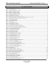
11. LIST OF TABLES
Table 3-1 Specific Gravity of Selected Gases................................................................................................................................................. 17
Table 3-2 Minimum Wire Gauges.................................................................................................................................................................. 17
Table 3-3 Sensor Module Wiring................................................................................................................................................................... 18
Table 3-4 Sensor Module Binary Switch Positions........................................................................................................................................ 18
Table 3-5 Sentry Controller Capacity............................................................................................................................................................. 19
Table 3-6 Sentry Enclosure Options............................................................................................................................................................... 19
Table 3-7 Sentry Power Load......................................................................................................................................................................... 20
Table 4-1 Display Conditions......................................................................................................................................................................... 36
Table 4-2 Sentry Primary Menu Selection............................................................................................................................................................. 37
Table 5-1 Calibration Gas Flow Rates............................................................................................................................................................ 51
Table 7-1 Sentry Error and Diagnostic Messages........................................................................................................................................... 63
Table 7-2 Diagnostic Report Description....................................................................................................................................................... 65
Table 7-3 Hydrogen Sulfide Sensor Wiring Pin-Out...................................................................................................................................... 67
Table 7-4 Heater Voltage and Current Settings.............................................................................................................................................. 68
Table 7-5 Combustible Gas Sensor Wiring Pin Out....................................................................................................................................... 70
Table 8-1 Toxic Sensor Cross Sensitivity....................................................................................................................................................... 87
Table 8-2 Individual Alarm Relay Logic...................................................................................................................................................... 100


