SMC sierra monitor corporation Sentry Instruction Manual - Version 6
INSTALLATION
Page: 17
3. INSTALLATION
NOTE
All systems are factory are pre-configured and calibrated.
All sensors are tagged to indicate the controller (alpha)
and the sensor module number (1 - 8).
Identify all components of the system during unpacking
and install using the factory configuration.
The system will power up in a calibrated and fully
functional condition.
3.1 CONTROLLER LOCATION
Rack mounted controllers should be installed in a control
room environment where they will be relatively free from
dust and temperature extremes. For ease of operation
select a rack window space at approximately eye level.
Four controllers can be installed side by side in a 19"
instrument shelf.
Enclosed controllers for outdoor applications should be
located in the most protected location available with
consideration for easy access for installation and
calibration. The enclosures should be mounted on a
vertical surface with the key board at approximately eye
level. The enclosure should not face directly into the sun.
3.2 SENSOR MODULE LOCATIONS
Select locations for each of the sensor modules based on
the following:
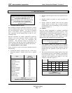
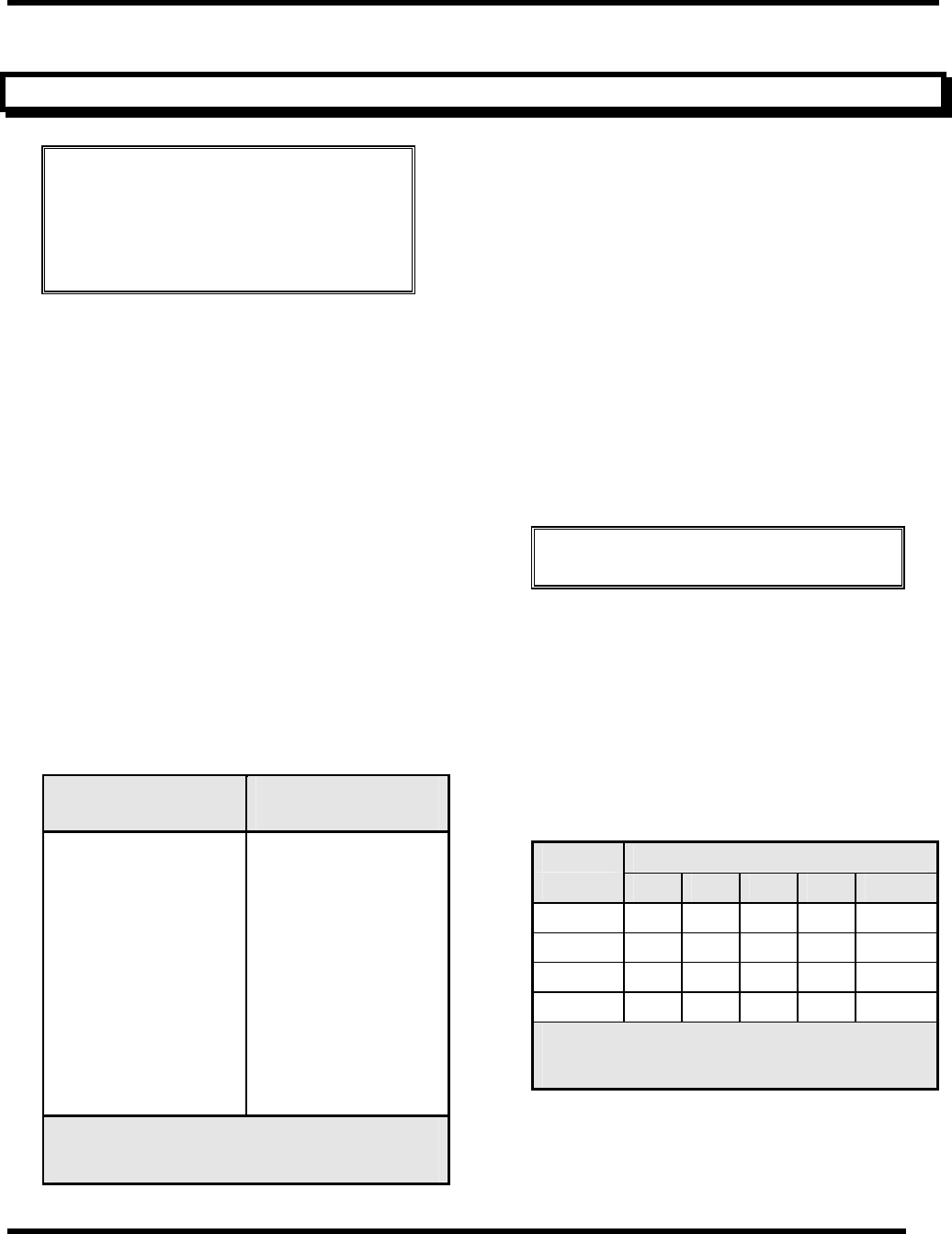
• Consider the density, relative to dry air, of the gas to
determine height of module above floor or ground
level:
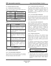
Gas Density
(Air = 1.00)
Air 1.00
Ammonia 0.60
Carbon Monoxide 0.97
Chlorine 2.49
Ethylene Oxide 1.52
Hydrogen 0.07
Hydrogen Chloride 1.27
Hydrogen Cyanide 0.94
Hydrogen Sulfide 1.19
Methane 0.55
Nitrogen Dioxide 1.58
Oxygen (Air) 1.10
Sulfur Dioxide 2.26
Table 3-1
Specific Gravity of Selected Gases
• Modules should be placed close to the potential source
of gas.
• Modules should be placed in areas accessible for
calibration.
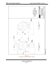
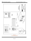
• Sensors should be pointed down and the conduit
should include an inverse trap to reduce moisture
(condensation) from accumulating in the electronics
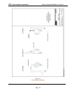
enclosure Figure 3-3.
3.3 WIRING
Plan the wiring arrangement to minimize installation
expense but with redundancy for critical locations. Wire
shall be Belden (or equivalent) 949X (where X = 2, 3, 4, or
5 depending on wire gauge). If high RFI or EMI levels
exist wiring should be protected by conduit or shield.
Shielded wire shall be Belden (or equivalent) 936X.
NOTE
In no case should the drain wire of shielded cable be used
as one of the conductors.
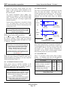
• Any modules which are located in a common
geographical area a long distance from the controller
can be connected to the same three conductor wire run
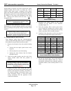
installed from the controller to that area. Table 3-2,
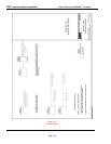
Figure 3-4.
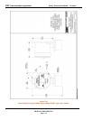
• The remote auxiliary power supply option can be used
for installation of one or more modules a long distance
from the controller location. The connection from the
controller to the remote power supply is via a two
conductor "data link" Figure 3-4.
Number of Maximum length of wire run (feet)
modules 500 1,000 2,000 3,000 5,000
1
20 20 18 16 14
2
20 18 14 12 xx
3
18 16 12 xx xx
4
16 14 12 xx xx
Table 3-2
Minimum Wire Gauges


