


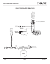

DV425TR DIRECT VENT ROOM HEATER
02/01 Page 54 250-5533
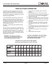
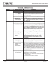
TROUBLE SHOOTING
Problem: Possible Cause: Solutions:
Pilot will not light. Air in Gas Lines. Bleed air from Gas Line.
Wrong Inlet Pressure. Check Gas Line pressure (7” Nat., 11” L.P.).
Defective Spark Replace Electrode if the Insulator is cracked or the Tip is
Electrode. corroded. Verify that the Spark Gap between the Pilot and
the Electrodes correct.
Defective Piezo Wire. Replace Piezo Wire if Insulation is damaged, broken, or
corroded.
Safety Interlock Allow Thermocouple to cool until the mV drops below the
Function engaged. hold - in requirements of the Safety Magnet (30 seconds or
less). Relight Pilot.
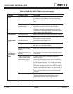
Pilot will not hold. Wrong Inlet Pressure. Check Gas Line pressure (7” Nat., 11” L.P.).
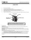
Pilot Adjustment Screw After the Pilot has been lit for approximately [3] min., and only
not adjusted properly. the Thermo-generator wires connected to the Main Operator
Head, measure the voltage across TPTH and TP. This Open
Circuit voltage should be between 500mV and 750mV. Tune
the Pilot Adjustment Screw until the mV reading falls within
these parameters. Counter-clockwise increases the mV
reading, Clockwise decreases it. Turn with a Wrench.
Thermocouple or With the Thermocouple and Thermo-generator Tips cool,
Thermo-generator has clean the upper 3/8” with a very fine Emery cloth.
Film build-up on Tip.
Electrical Resistance Using a very fine Emery cloth, clean the Thermo-generator
too high. and Thermocouple connections at the Valve. Tighten
Thermocouple into Valve, hand tight, adding a 1/4 turn
with a wrench.
Defective Verify that the Thermocouple is not kinked or damaged.
Thermocouple. Check Open-Circuit voltage of Thermocouple. Voltage should
(mV Plus System) be between 18mv and 28mv. If voltage is less than 14mv,
replace the Thermocouple.
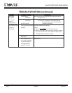
Defective Thermo- After the Pilot has been lit for approximately [3] min.,and only
generator. the Thermo-generator wires connected to the Main Operator H
(millivolt System) Head, measure the voltage across TPTH and TP. This Open
Circuit voltage should be between 500mV and 750mV. Tune
the Pilot Adjustment Screw until the mV reading falls within
these parameters. Counter-Clockwise increases mV reading,
Clockwise decreases it.
Defective Safety Magnet Verify operation of Safety Magnet in the following manner:
(mV Plus Systems). (A) Depress and hold the Pilot Button.
(B) Verify Open-Circuit Thermocouple voltage as described
in previous Step.
(C) Reconnect Thermocouple to the Valve.