


DV425TR DIRECT VENT ROOM HEATER
02/01 Page 34 250-5533
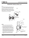
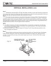
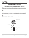
Step 4.
Assemble the desired lengths of GS pipe and elbows necessary to reach from the stove up through the
round support box. Ensure that all pipe and elbow connections are in their fully twist-locked position. Be sure to
seal the outer pipe with appropriate sealant (high temperature silicone).
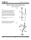
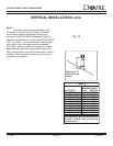
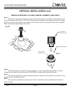
Step 5.
Cut a hole in the roof centered on the small drill hole placed in the roof in Step 2. The hole should be
of sufficient size to meet the minimum requirements for clearance to combustibles, as specified. Continue to
assemble lengths of pipe and elbows necessary to reach from the ceiling support box up through the roof line.
Galvanized pipe and elbows may be utilized in the attic, as well as above the roofline. The galvanized finish is
desirable above the roofline, due to its higher corrosion resistance.
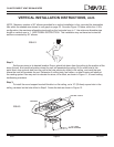
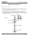
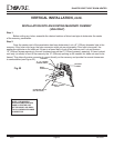
NOTE:
(1) If an offset is necessary in the attic to avoid obstructions, it is important to support the vent pipe every
3’ (91.4cm) to avoid excessive stress on the elbows, and possible separation. Wall straps are available
for this purpose (page 32, Figure 11).
(2) Whenever possible, use 45° elbows, instead of 90° elbows. The 45° elbow offers less restriction to the
flow of flue gases and intake air.
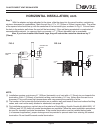
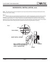
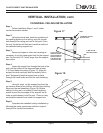
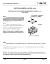
Step 6.
Slip the flashing over the pipe section(s) protruding through the roof. Secure the base of the flashing
to the roof with roofing nails. Ensure the roofing material overlaps the top edge of the flashing as shown
in Figure 14. Verify that the chimney is the required height above the roof. See Roof Pitch Table on page
35 of this manual
VERTICAL INSTALLATION, cont.
Fig. 14
SHINGLES OVERLAP ON
TOP EDGE OF FLASHING
CAP AND STORM
COLLAR
NOT SHOWN FOR
CLARITY